HYBRID CONTROL SYSTEM, Diagnostic DTC:P0848-540

| DTC Code | DTC Name |
|---|---|
| P0848-540 | Transmission Fluid Pressure Sensor/Switch "B" Circuit High |
DESCRIPTION
Refer to the description for DTC P0731-871 Click here.
| DTC No. | INF Code | DTC Detection Condition | Trouble Area |
|---|---|---|---|
| P0848 | 540 | Malfunction in the oil pressure sensor circuit (open circuit) |
|
WIRING DIAGRAM
Refer to the wiring diagram for DTC P0731-871 Click here.
INSPECTION PROCEDURE
PROCEDURE
-
CHECK DTC OUTPUT (HYBRID CONTROL)
-
Connect the GTS to the DLC3.
-
Turn the power switch on (IG).
-
Enter the following menus: Powertrain / Hybrid Control / Trouble Codes.
-
Check if DTCs are output.
Result Result Proceed to P0848-540 only is output. A Any of the following DTCs are also output. B DTC No. Relevant Diagnosis P0731-871 Gear 1 Incorrect Ratio P06A4-209 Sensor Reference Voltage "D" Circuit Low P06A5-210 Sensor Reference Voltage "D" Circuit High -
Turn the power switch off.
B 
GO TO DTC CHART (HYBRID CONTROL SYSTEM) Click here
A 
-
-
CHECK CONNECTOR CONNECTION CONDITION (POWER MANAGEMENT CONTROL ECU CONNECTOR)
-
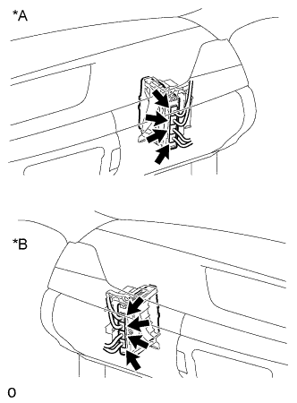
Text in Illustration *A for LHD *B for RHD Check the connector connections and contact pressure of the relevant terminals for the power management control ECU connectors Click here.
OK The connectors are connected securely and there are no contact pressure problems.
NG
CONNECT SECURELY
OK
-
-
CHECK CONNECTOR CONNECTION CONDITION (OIL PRESSURE SENSOR)
-
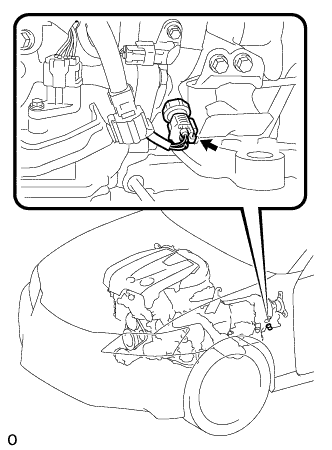
Check the connection of the oil pressure sensor connector Click here.
OK The connector is connected securely and there are no contact problems.
NG
CONNECT SECURELY
OK
-
-
READ VALUE USING GTS (POWER SUPPLY SENSOR VOLTAGE)
-
Connect the GTS to the DLC3.
-
Turn the power switch on (IG).
-
Enter the following menus: Powertrain / Hybrid Control / Data List / Power Supply Sensor Voltage.
-
Read the Data List.
OK Tester Display Switch Condition Specified Condition Power Supply Sensor Voltage Power switch on (IG) 4.75 to 5.25 V -
Turn the power switch off.
NG
REPLACE POWER MANAGEMENT CONTROL ECU Click here
OK
-
-
CHECK POWER MANAGEMENT CONTROL ECU (VOLTAGE)
-
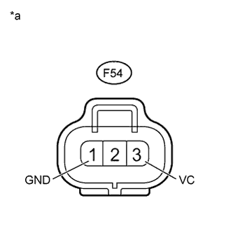
Text in Illustration *a Front view of wire harness connector
(to Oil Pressure Sensor)
Disconnect the oil pressure sensor connector.
-
Turn the power switch on (IG).
-
Measure the voltage according to the value(s) in the table below.
Standard Voltage Tester Connection Switch Condition Specified Condition F54-3 (VC) - F54-1 (GND) Power switch on (IG) 4.75 to 5.25 V -
Turn the power switch off.
-
Connect the oil pressure sensor connector.
NG 
OK
-
-
READ VALUE USING GTS (B2 OIL PRESSURE SENSOR)
-
Connect the GTS to the DLC3.
-
Turn the power switch on (IG).
-
Enter the following menus: Powertrain / Hybrid Control / Data List / Power Supply Sensor Voltage.
-
Read the Data List.
OK Tester Display Switch Condition Specified Condition Power Supply Sensor Voltage Power switch on (IG) 4.75 to 5.25 V -
Turn the power switch off.
NG
OK
-
-
CHECK HYBRID VEHICLE TRANSMISSION ASSEMBLY (OIL PRESSURE SENSOR)
-
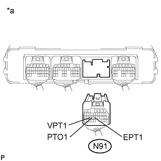
Text in Illustration *a Rear view of wire harness connector
(to Power Management Control ECU)
Disconnect the connector from the power management control ECU.
-
Measure the resistance according to the value(s) in the table below.
Standard Resistance Tester Connection Condition Specified Condition N91-25 (VPT1) - N91-24 (PTO1) 68°F (20°C) 1.0 to 4.0 Ω N91-24 (PTO1) - N91-23 (EPT1) 68°F (20°C) 5.0 to 10.0 Ω -
Connect the power management control ECU connector.
NG
REPLACE OIL PRESSURE SENSOR Click here
OK
-
-
CLEAR DTC
-
Connect the GTS to the DLC3.
-
Turn the power switch on (IG).
-
Enter the following menus: Powertrain / Hybrid Control / Trouble Codes.
-
Read and record the DTCs and freeze frame data.
-
Clear DTCs and freeze frame data.
-
Turn the power switch off.
NEXT
-
-
CHECK DTC OUTPUT (HYBRID CONTROL)
-
Connect the GTS to the DLC3.
-
Turn the power switch on (READY).
-
Enter the following menus: Powertrain / Hybrid Control / Trouble Codes.
-
Check if DTCs are output.
Result Result Proceed to P0848-540 is not output. A P0848-540 is output. B Note
This DTC is not output when the power switch is on (IG). Therefore, make sure to perform the inspection with the power switch on (READY).
-
Turn the power switch off.
B
REPLACE POWER MANAGEMENT CONTROL ECU Click here
A
-
-
CHECK FLUID LEAKS
-
Check for fluid leaks from the hybrid vehicle transmission assembly.
OK There are no fluid leaks.
NG
REPAIR OR REPLACE HYBRID VEHICLE TRANSMISSION ASSEMBLY Click here
OK 
CHECK FOR INTERMITTENT PROBLEMS Click here
-
-
CHECK HARNESS AND CONNECTOR (POWER MANAGEMENT CONTROL ECU - OIL PRESSURE SENSOR)
-
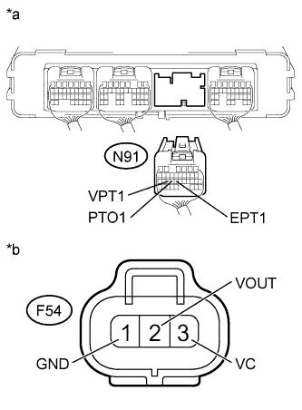
Text in Illustration *a Rear view of wire harness connector
(to Power Management Control ECU)
*b Front view of wire harness connector
(to Oil Pressure Sensor)
Disconnect the oil pressure sensor connector.
-
Disconnect the power management control ECU connector.
-
Measure the resistance according to the value(s) in the table below.
Standard Resistance Tester Connection Switch Condition Specified Condition N91-25 (VPT1) - F54-3 (VC) Power switch off Below 1 Ω N91-24 (PTO1) - F54-2 (VOUT) Power switch off Below 1 Ω N91-23 (EPT1) - F54-1 (GND) Power switch off Below 1 Ω N91-25 (VPT1) - Body ground Power switch off 10 kΩ or higher N91-24 (PTO1) - Body ground Power switch off 10 kΩ or higher N91-23 (EPT1) - Body ground Power switch off 10 kΩ or higher -
Connect the oil pressure sensor connector.
-
Connect the power management control ECU connector.
NG
REPAIR OR REPLACE HARNESS OR CONNECTOR
OK
REPLACE POWER MANAGEMENT CONTROL ECU Click here
-