HYBRID CONTROL SYSTEM, Diagnostic DTC:P0732-867, P0732-868

| DTC Code | DTC Name |
|---|---|
| P0732-867 | Gear 2 Incorrect Ratio |
| P0732-868 | Gear 2 Incorrect Ratio |
DESCRIPTION
Refer to the description for DTC P0731-871 Click here.
Tech Tips
Although the DTC title indicates an incorrect gear ratio, this DTC relates to a malfunction of the B1 hydraulic circuit.
| DTC No. | INF Code | DTC Detection Condition | Trouble Area |
|---|---|---|---|
| P0732 | 867 | Even if the fluid pressure was applied for high gear after the ST-on state occurred, the power management control ECU is not able to confirm that the fluid pressure was applied to the B1 circuit within the specified time. |
|
| P0732 | 868 | When upshifting: After shifting is completed, the power management control ECU is not able to confirm that the fluid pressure was applied to the B1 circuit within the specified time. |
Tech Tips
ST-on is a state that occurs when the READY indicator in the combination meter blinks after the power switch is pressed with the brake pedal depressed.
WIRING DIAGRAM
Refer to the wiring diagram for DTC P0731-871 Click here.
INSPECTION PROCEDURE
PROCEDURE
-
CHECK DTC OUTPUT (HYBRID CONTROL)
-
Connect the GTS to the DLC3.
-
Turn the power switch on (IG).
-
Enter the following menus: Powertrain / Hybrid Control / Trouble Codes.
-
Check if DTCs are output.
Result Result Proceed to P0732-867 or P0732-868 only is output. A Any of the following DTCs are also output. B DTC No. Relevant Diagnosis P0748-850 Pressure Control Solenoid "A" Electrical (Shift Solenoid Valve (SL1)) P0778-851 Pressure Control Solenoid "B" Electrical (Shift Solenoid Valve (SL2)) -
Turn the power switch off.
B 
GO TO DTC CHART (HYBRID CONTROL SYSTEM) Click here
A 
-
-
CHECK CONNECTOR CONNECTION CONDITION (POWER MANAGEMENT CONTROL ECU CONNECTOR)
-
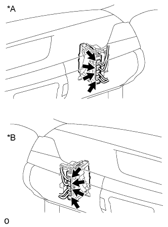
Text in Illustration *A for LHD *B for RHD Check the connector connections and contact pressure of the relevant terminals for the power management control ECU connectors Click here.
OK The connectors are connected securely and there are no contact pressure problems.
NG
CONNECT SECURELY
OK
-
-
CHECK CONNECTOR CONNECTION CONDITION (TRANSMISSION WIRE CONNECTOR)
-
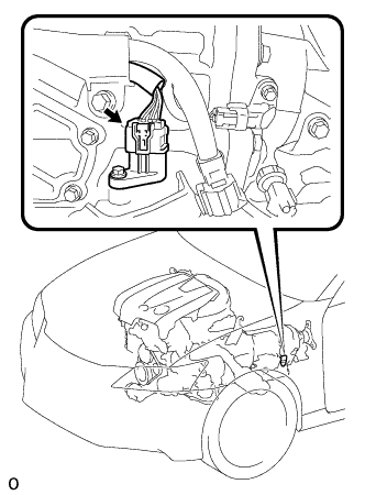
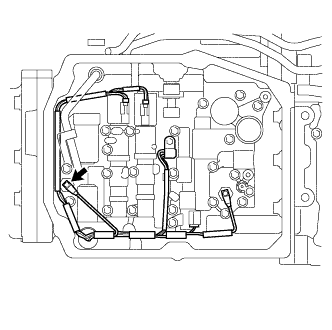
Check the connection of the transmission wire connector Click here.
OK The connector is connected securely and there are no contact problems.
NG
CONNECT SECURELY
OK
-
-
CHECK HYBRID VEHICLE TRANSMISSION ASSEMBLY (SOLENOID VALVE (SL1), SOLENOID VALVE (SL2) AND OIL PRESSURE SWITCH (PB1))
-
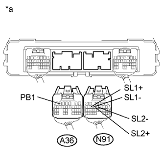
Text in Illustration *a Rear view of wire harness connector
(to Power Management Control ECU)
Disconnect the connector from the power management control ECU.
-
Measure the resistance according to the value(s) in the table below.
Standard Resistance Tester Connection Condition Specified Condition N91-14 (SL1+) - N91-13 (SL1-) 68°F (20°C) 5.0 to 5.6 Ω N91-12 (SL2+) - N91-11 (SL2-) 68°F (20°C) 5.0 to 5.6 Ω Standard Resistance Tester Connection Switch Condition Specified Condition A36-6 (PB1) - Body ground Power switch off 10 kΩ or higher Result Result Proceed to Normal A Oil pressure switch (PB1) result is not as specified B Solenoid valve (SL1 or SL2) result is not as specified C -
Connect the power management control ECU connector.
B 
CHECK HARNESS AND CONNECTOR (POWER MANAGEMENT CONTROL ECU - TRANSMISSION WIRE) Click here
C
CHECK HARNESS AND CONNECTOR (POWER MANAGEMENT CONTROL ECU - TRANSMISSION WIRE) Click here
A
-
-
READ VALUE USING GTS (B1 OIL PRESSURE)
-
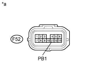
Text in Illustration *a Front view of wire harness connector
(to Transmission Wire)
Disconnect the transmission wire connector.
-
Connect the GTS to the DLC3.
-
Turn the power switch on (IG).
Note
Turning the power switch on (IG) with the transmission wire connector disconnected causes other DTCs to be stored. Clear the DTCs after performing this inspection.
-
Enter the following menus: Powertrain / Hybrid Control / Data List / B1 Oil Pressure.
-
Read the Data List.
OK Tester Display Condition Specified Condition B1 Oil Pressure F52-11 (PB1) is connected to body ground ON F52-11 (PB1) is not connected to body ground OFF -
Turn the power switch off.
-
Connect the transmission wire connector.
NG
CHECK HARNESS AND CONNECTOR (POWER MANAGEMENT CONTROL ECU - TRANSMISSION WIRE) Click here
OK
-
-
CLEAR DTC
-
Connect the GTS to the DLC3.
-
Turn the power switch on (IG).
-
Enter the following menus: Powertrain / Hybrid Control / Trouble Codes.
-
Read and record the DTCs and freeze frame data.
-
Clear DTCs and freeze frame data.
-
Turn the power switch off.
NEXT
-
-
SIMULATION TEST
-
Connect the GTS to the DLC3.
-
Turn the power switch on (IG).
-
Enter the following menus: Powertrain / Hybrid Control / Active Test / Activate the Oil Pump (500rpm), Activate the Oil Pump (1000rpm).
-
Select OPM Revolution in the Data List.
-
Perform the "Activate the Oil Pump (500rpm)" and "Activate the Oil Pump (1000rpm)" Active Tests.
OK For both the "Activate the Oil Pump (500rpm)" and "Activate the Oil Pump (1000rpm)" Active Tests, the value of "OPM Revolution" is almost the same as the corresponding Active Test speed. Note
Make sure that the auxiliary battery is not discharged.
-
Turn the power switch off.
NG
REPLACE HYBRID VEHICLE TRANSMISSION ASSEMBLY Click here
OK
-
-
CHECK FOR INTERMITTENT PROBLEMS
NG
REPAIR OR REPLACE MALFUNCTIONING PARTS, COMPONENT AND AREA
OK
-
CHECK FLUID LEAKS
-
Check for fluid leaks from the hybrid vehicle transmission assembly.
OK There are no fluid leaks.
NG
REPAIR OR REPLACE HYBRID VEHICLE TRANSMISSION ASSEMBLY Click here
OK
-
-
CHECK CONNECTOR CONNECTION CONDITION (OIL PRESSURE SWITCH (PB1))
-
Remove the oil strainer assembly Click here.
-
Check the connection of the oil pressure switch (PB1) connector Click here.
OK The connector is connected securely and there are no contact problems. -
Install the oil strainer assembly.
NG
CONNECT SECURELY
OK
-
-
CHECK TRANSMISSION WIRE
-
Remove the oil strainer assembly Click here.
-
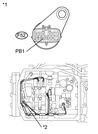
Text in Illustration *1 Transmission Wire *2 Oil Pressure Switch (PB1) Disconnect the transmission wire connector.
-
Disconnect the connector from the oil pressure switch (PB1).
-
Turn the power switch on (IG).
-
Measure the voltage according to the value(s) in the table below.
Standard Voltage Tester Connection Switch Condition Specified Condition F52-11 (PB1) - Body ground Power switch on (IG) Below 1 V Note
Turning the power switch on (IG) with the transmission wire connector disconnected causes other DTCs to be stored. Clear the DTCs after performing this inspection.
-
Turn the power switch off.
-
Measure the resistance according to the value(s) in the table below.
Standard Resistance Tester Connection Switch Condition Specified Condition F52-11 (PB1) - Transmission wire oil pressure switch (PB1) side Power switch off Below 1 Ω F52-11 (PB1) or Transmission wire oil pressure switch (PB1) side - Body ground and other terminals Power switch off 10 kΩ or higher -
Connect the transmission wire connector.
-
Connect the connector to the oil pressure switch (PB1).
-
Install the oil strainer assembly.
NG
REPLACE TRANSMISSION WIRE Click here
OK 
REPLACE OIL PRESSURE SWITCH (PB1) Click here
-
-
CHECK HARNESS AND CONNECTOR (POWER MANAGEMENT CONTROL ECU - TRANSMISSION WIRE)
-
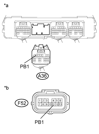
Text in Illustration *a Rear view of wire harness connector
(to Power Management Control ECU)
*b Front view of wire harness connector
(to Transmission Wire)
Disconnect the transmission wire connector.
-
Disconnect the connector from the power management control ECU.
-
Turn the power switch on (IG).
-
Measure the voltage according to the value(s) in the table below.
Standard Voltage Tester Connection Switch Condition Specified Condition A36-6 (PB1) - Body ground Power switch on (IG) Below 1 V Note
Turning the power switch on (IG) with the power management control ECU connector disconnected causes other DTCs to be stored. Clear the DTCs after performing this inspection.
-
Turn the power switch off.
-
Measure the resistance according to the value(s) in the table below.
Standard Resistance Tester Connection Switch Condition Specified Condition A36-6 (PB1) - F52-11 (PB1) Power switch off Below 1 Ω A36-6 (PB1) or F52-11 (PB1) - Body ground and other terminals Power switch off 10 kΩ or higher -
Connect the transmission wire connector.
-
Connect the power management control ECU connector.
NG
REPAIR OR REPLACE HARNESS OR CONNECTOR
OK
-
-
CHECK CONNECTOR CONNECTION CONDITION (OIL PRESSURE SWITCH (PB1))
-
Remove the oil strainer assembly Click here.
-
Check the connection of the oil pressure switch (PB1) connector Click here.
OK The connector is connected securely and there are no contact problems. -
Install the oil strainer assembly.
NG
CONNECT SECURELY
OK
-
-
CHECK TRANSMISSION WIRE
-
Remove the oil strainer assembly Click here.
-
Text in Illustration *1 Transmission Wire *2 Oil Pressure Switch (PB1) Disconnect the connector from the transmission wire.
-
Disconnect the connector from the oil pressure switch (PB1).
-
Turn the power switch on (IG).
-
Measure the voltage according to the value(s) in the table below.
Standard Voltage Tester Connection Switch Condition Specified Condition F52-11 (PB1) - Body ground Power switch on (IG) Below 1 V Note
Turning the power switch on (IG) with the transmission wire connector disconnected causes other DTCs to be stored. Clear the DTCs after performing this inspection.
-
Turn the power switch off.
-
Measure the resistance according to the value(s) in the table below.
Standard Resistance Tester Connection Switch Condition Specified Condition F52-11 (PB1) - Transmission wire oil pressure switch (PB1) side Power switch off Below 1 Ω F52-11 (PB1) or Transmission wire oil pressure switch (PB1) side - Body ground and other terminals Power switch off 10 kΩ or higher -
Connect the transmission wire connector.
-
Connect the connector to the oil pressure switch (PB1).
-
Install the oil strainer assembly.
NG
REPLACE TRANSMISSION WIRE Click here
OK
REPLACE OIL PRESSURE SWITCH (PB1) Click here
-
-
CHECK HARNESS AND CONNECTOR (POWER MANAGEMENT CONTROL ECU - TRANSMISSION WIRE)
-
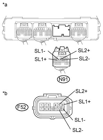
Text in Illustration *a Rear view of wire harness connector
(to Power Management Control ECU)
*b Front view of wire harness connector
(to Transmission Wire)
Disconnect the connector from the power management control ECU.
-
Disconnect the transmission wire connector.
-
Turn the power switch on (IG).
-
Measure the voltage according to the value(s) in the table below.
Standard Voltage Tester Connection Switch Condition Specified Condition N91-13 (SL1-) - Body ground Power switch on (IG) Below 1 V N91-14 (SL1+) - Body ground Power switch on (IG) Below 1 V N91-11 (SL2-) - Body ground Power switch on (IG) Below 1 V N91-12 (SL2+) - Body ground Power switch on (IG) Below 1 V Note
Turning the power switch on (IG) with the power management control ECU connector disconnected causes other DTCs to be stored. Clear the DTCs after performing this inspection.
-
Turn the power switch off.
-
Measure the resistance according to the value(s) in the table below.
Standard Resistance Tester Connection Switch Condition Specified Condition N91-13 (SL1-) - F52-13 (SL1-) Power switch off Below 1 Ω N91-14 (SL1+) - F52-6 (SL1+) Power switch off Below 1 Ω N91-11 (SL2-) - F52-12 (SL2-) Power switch off Below 1 Ω N91-12 (SL2+) - F52-5 (SL2+) Power switch off Below 1 Ω N91-13 (SL1-) or F52-13 (SL1-) - Body ground and other terminals Power switch off 10 kΩ or higher N91-14 (SL1+) or F52-6 (SL1+) - Body ground and other terminals Power switch off 10 kΩ or higher N91-11 (SL2-) or F52-12 (SL2-) - Body ground and other terminals Power switch off 10 kΩ or higher N91-12 (SL2+) or F52-5 (SL2+) - Body ground and other terminals Power switch off 10 kΩ or higher Tech Tips
The solenoid valve (SL1 or SL2) is not available separately. If it requires replacement, replace the hybrid vehicle transmission assembly.
-
Connect the power management control ECU connector.
-
Connect the transmission wire connector.
NG
REPAIR OR REPLACE HARNESS OR CONNECTOR
OK
REPLACE HYBRID VEHICLE TRANSMISSION ASSEMBLY Click here
-
-
CHECK HARNESS AND CONNECTOR (POWER MANAGEMENT CONTROL ECU - TRANSMISSION WIRE)
-
Text in Illustration *a Rear view of wire harness connector
(to Power Management Control ECU)
*b Front view of wire harness connector
(to Transmission Wire)
Disconnect the transmission wire connector.
-
Disconnect the connector from the power management control ECU.
-
Turn the power switch on (IG).
-
Measure the voltage according to the value(s) in the table below.
Standard Voltage Tester Connection Switch Condition Specified Condition A36-6 (PB1) - Body ground Power switch on (IG) Below 1 V Note
Turning the power switch on (IG) with the power management control ECU connector disconnected causes other DTCs to be stored. Clear the DTCs after performing this inspection.
-
Turn the power switch off.
-
Measure the resistance according to the value(s) in the table below.
Standard Resistance Tester Connection Switch Condition Specified Condition A36-6 (PB1) - F52-11 (PB1) Power switch off Below 1 Ω A36-6 (PB1) or F52-11 (PB1) - Body ground and other terminals Power switch off 10 kΩ or higher -
Connect the power management control ECU connector.
-
Connect the transmission wire connector.
NG
REPAIR OR REPLACE HARNESS OR CONNECTOR
OK
REPLACE POWER MANAGEMENT CONTROL ECU Click here
-