HYBRID CONTROL SYSTEM, Diagnostic DTC:P0712-856, P0713-857

| DTC Code | DTC Name |
|---|---|
| P0712-856 | Transmission Fluid Temperature Sensor "A" Circuit Low Input |
| P0713-857 | Transmission Fluid Temperature Sensor "A" Circuit High Input |
DESCRIPTION
-
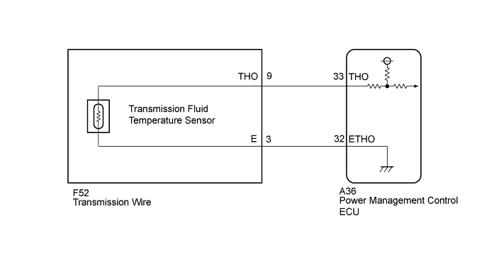
The transmission fluid temperature sensor, which is installed in the valve body, is used to detect the fluid temperature of the transmission fluid pressure control circuit. The sensor signal is used by the power management control ECU to determine transmission fluid temperature.
-
Characteristics of the thermistor resistance (reference values) are as follows.
| Terminal | THO (with connector disconnected) |
Resistance | Transmission Fluid Temperature |
|---|---|---|---|
| THO - E | 4.5 to 5.5 V | 5.0 to 8.0 kΩ | Approximately 50°F (10°C) |
| 0.22 to 0.28 kΩ | Approximately 230°F (110°C) |
| DTC No. | INF Code | DTC Detection Condition | Trouble Area |
|---|---|---|---|
| P0712 | 856 | Malfunction in the transmission fluid temperature sensor circuit (short circuit) |
|
| P0713 | 857 | Malfunction in the transmission fluid temperature sensor circuit (open circuit) |
|
WIRING DIAGRAM
INSPECTION PROCEDURE
Tech Tips
Read the freeze frame data using the GTS. In the freeze frame data, some information is recorded about the engine conditions at the moment a malfunction occurs. This information can be helpful when troubleshooting.
PROCEDURE
-
READ VALUE USING GTS (T/M OIL TEMPERATURE)
-
Connect the GTS to the DLC3.
-
Turn the power switch on (IG).
-
Enter the following menus: Powertrain / Hybrid Control / Data List / T/M Oil Temperature.
-
Read the Data List.
OK Tester Display Condition Tester Display T/M Oil Temperature Vehicle has been left for 24 hours Approximately equal to ambient temperature -
Turn the power switch off.
NG 
OK 
-
-
CHECK FOR INTERMITTENT PROBLEMS
NG 
REPAIR OR REPLACE MALFUNCTIONING PARTS, COMPONENT AND AREA
OK 
REPLACE POWER MANAGEMENT CONTROL ECU Click here
-
CHECK CONNECTOR CONNECTION CONDITION (POWER MANAGEMENT CONTROL ECU CONNECTOR)
-
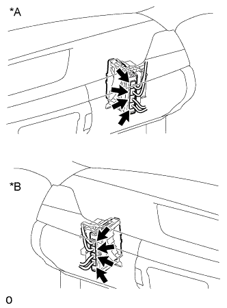
Text in Illustration *A for LHD *B for RHD Check the connector connections and contact pressure of the relevant terminals for the power management control ECU connectors Click here.
OK The connectors are connected securely and there are no contact pressure problems.
NG
CONNECT SECURELY
OK
-
-
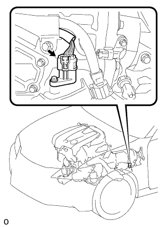
CHECK TRANSMISSION WIRE (TRANSMISSION FLUID TEMPERATURE SENSOR)
-
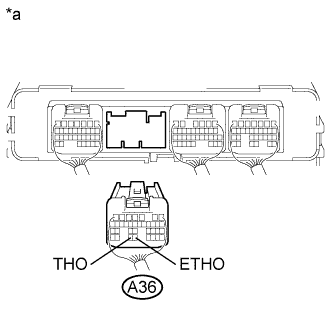
Text in Illustration *a Rear view of wire harness connector
(to Power Management Control ECU)
Disconnect the connector from the power management control ECU.
-
Measure the resistance according to the value(s) in the table below.
Standard Resistance Tester Connection Condition Specified Condition A36-33 (THO) - A36-32 (ETHO) 50°F (10°C) 5.0 to 8.0 kΩ A36-33 (THO) - A36-32 (ETHO) 230°F (110°C) 0.22 to 0.28 kΩ -
Turn the power switch on (IG).
-
Measure the voltage according to the value(s) in the table below.
Standard Voltage Tester Connection Switch Condition Specified Condition A36-33 (THO) - Body ground Power switch on (IG) Below 1 V Note
Turning the power switch on (IG) with the power management control ECU connectors disconnected causes other DTCs to be stored. Clear the DTCs after performing this inspection.
-
Turn the power switch off.
-
Measure the resistance according to the value(s) in the table below.
Standard Resistance Tester Connection Switch Condition Specified Condition A36-33 (THO) - Body ground and other terminals Power switch off 10 kΩ or higher A36-32 (ETHO) - Body ground and other terminals Power switch off 10 kΩ or higher -
Connect the power management control ECU connector.
NG
CHECK CONNECTOR CONNECTION CONDITION (TRANSMISSION WIRE CONNECTOR) Click here
OK
-
-
CHECK FOR INTERMITTENT PROBLEMS
NG
REPAIR OR REPLACE MALFUNCTIONING PARTS, COMPONENT AND AREA
OK
REPLACE POWER MANAGEMENT CONTROL ECU Click here
-
CHECK CONNECTOR CONNECTION CONDITION (TRANSMISSION WIRE CONNECTOR)
-
Check the connection of the transmission wire connector Click here.
OK The connector is connected securely and there are no contact problems.
NG
CONNECT SECURELY
OK
-
-
CHECK HARNESS AND CONNECTOR (POWER MANAGEMENT CONTROL ECU - TRANSMISSION WIRE)
-
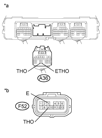
Text in Illustration *a Rear view of wire harness connector
(to Power Management Control ECU)
*b Front view of wire harness connector
(to Transmission Wire)
Disconnect the power management control ECU connector.
-
Disconnect the transmission wire connector.
-
Turn the power switch on (IG).
-
Measure the voltage according to the value(s) in the table below.
Standard Voltage Tester Connection Switch Condition Specified Condition A36-33 (THO) - Body ground Power switch on (IG) Below 1 V A36-32 (ETHO) - Body ground Power switch on (IG) Below 1 V Note
Turning the power switch on (IG) with the power management control ECU connectors disconnected causes other DTCs to be stored. Clear the DTCs after performing this inspection.
-
Turn the power switch off.
-
Measure the resistance according to the value(s) in the table below.
Standard Resistance Tester Connection Switch Condition Specified Condition A36-33 (THO) - F52-9 (THO) Power switch off Below 1 Ω A36-32 (ETHO) - F52-3 (E) Power switch off Below 1 Ω A36-33 (THO) or F52-9 (THO) - Body ground and other terminals Power switch off 10 kΩ or higher A36-32 (ETHO) or F52-3 (E) - Body ground and other terminals Power switch off 10 kΩ or higher -
Connect the power management control ECU connector.
-
Connect the transmission wire connector.
NG
REPAIR OR REPLACE HARNESS OR CONNECTOR
OK
REPLACE TRANSMISSION WIRE Click here
-