HYBRID CONTROL SYSTEM Transmission Control Switch Circuit
DESCRIPTION
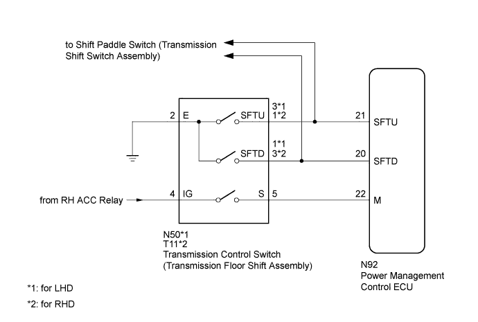
When the shift lever is in S, the shift range position can be changed freely using the sequential gate of the transmission floor shift assembly.
WIRING DIAGRAM
INSPECTION PROCEDURE
PROCEDURE
-
READ VALUE USING GTS (SPORTS MODE)
-
Connect the GTS to the DLC3.
-
Turn the power switch on (IG).
-
Enter the following menus: Powertrain / Hybrid Control / Data List / Sports Mode.
-
Read the value displayed on the GTS.
Tester Display Measurement Item/Range Normal Condition Sports Mode Sports shift signal/
ON or OFF
Shift lever in S:
ON
Shift lever not in S:
OFF
Result Result Proceed to The GTS display changes according to the shift lever operation. A The GTS display does not change according to the shift lever operation. B -
Turn the power switch off.
B 
CHECK HARNESS AND CONNECTOR (POWER SOURCE CIRCUIT) Click here
A 
-
-
READ VALUE USING GTS (SPORT UP SHIFT SENS STATE, SPORT DWN SHIFT SENS STATE)
-
Connect the GTS to the DLC3.
-
Turn the power switch on (IG).
-
Enter the following menus: Powertrain / Hybrid Control / Data List / Sport Up Shift Sens State, Sport Dwn Shift Sens State.
-
Read the value displayed on the GTS.
Tester Display Measurement Item/Range Normal Condition Sport Up Shift Sens State Sports shift UP signal/
ON or OFF
Shift lever in "+" or shift paddle switch RH operated:
ON
Shift lever in neutral or shift paddle switch RH not operated:
OFF
Sport Dwn Shift Sens State Sport shift DOWN signal/
ON or OFF
Shift lever in "-" or shift paddle switch LH operated:
ON
Shift lever in neutral or shift paddle switch LH not operated:
OFF
Result Result Proceed to The GTS display changes according to the shift lever operation. A The GTS display does not change according to the shift lever operation. B
B
INSPECT TRANSMISSION CONTROL SWITCH (TRANSMISSION FLOOR SHIFT ASSEMBLY) Click here
A
-
-
CHECK FOR INTERMITTENT PROBLEMS
NG 
REPAIR OR REPLACE MALFUNCTIONING PARTS, COMPONENT AND AREA
OK 
REPLACE POWER MANAGEMENT CONTROL ECU Click here
-
INSPECT TRANSMISSION CONTROL SWITCH (TRANSMISSION FLOOR SHIFT ASSEMBLY)
-
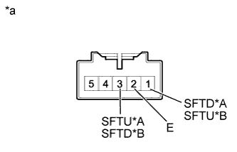
Text in Illustration *A for LHD *B for RHD *a Component without harness connected
(Transmission Control Switch)
Disconnect the N50*1 or T11*2 transmission control switch connector.
-
*1: for LHD
-
*2: for RHD
-
-
Measure the resistance according to the value(s) in the table below when the shift lever is moved to each position.
Standard Resistance for LHD Tester Connection Condition Specified Condition 3 (SFTU) - 2 (E) Press continuously
"+"
(Up shift)
Below 1 Ω 1 (SFTD) - 2 (E) Press continuously
"-"
(Down shift)
Below 1 Ω 3 (SFTU) - 2 (E) S 10 kΩ or higher 1 (SFTD) - 2 (E) S 10 kΩ or higher for RHD Tester Connection Condition Specified Condition 1 (SFTU) - 2 (E) Press continuously
"+"
(Up shift)
Below 1 Ω 3 (SFTD) - 2 (E) Press continuously
"-"
(Down shift)
Below 1 Ω 1 (SFTU) - 2 (E) S 10 kΩ or higher 3 (SFTD) - 2 (E) S 10 kΩ or higher -
Reconnect the N50*1 or T11*2 transmission control switch connector.
-
*1: for LHD
-
*2: for RHD
-
NG
REPLACE TRANSMISSION CONTROL SWITCH (TRANSMISSION FLOOR SHIFT ASSEMBLY) Click here
OK
-
-
CHECK HARNESS AND CONNECTOR (TRANSMISSION CONTROL SWITCH - POWER MANAGEMENT CONTROL ECU)
-
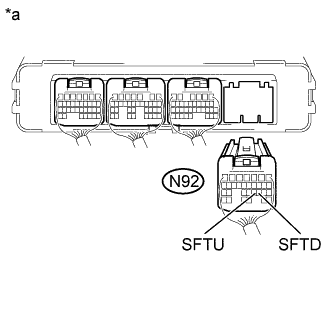
Text in Illustration *a Rear view of wire harness connector
(to Power Management Control ECU)
Disconnect the N92 power management control ECU connector.
-
Disconnect the N31 spiral cable sub-assembly connector.
-
Measure the resistance according to the value(s) in the table below when the shift lever is moved to each position.
Standard Resistance Tester Connection Condition Specified Condition N92-21 (SFTU) - Body ground Press continuously
"+"
(Up shift)
Below 1 Ω N92-20 (SFTD) - Body ground Press continuously
"-"
(Down shift)
Below 1 Ω N92-21 (SFTU) - Body ground S 10 kΩ or higher N92-20 (SFTD) - Body ground S 10 kΩ or higher -
Reconnect the N31 spiral cable sub-assembly connector.
-
Reconnect the N92 power management control ECU connector.
NG
REPAIR OR REPLACE HARNESS OR CONNECTOR
OK
REPLACE POWER MANAGEMENT CONTROL ECU Click here
-
-
CHECK HARNESS AND CONNECTOR (POWER SOURCE CIRCUIT)
-
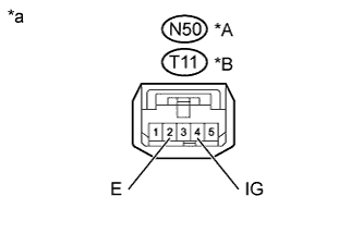
Text in Illustration *A for LHD *B for RHD *a Front view of wire harness connector
(to Transmission Control Switch)
Disconnect the N50*1 or T11*2 transmission control switch connector.
-
*1: for LHD
-
*2: for RHD
-
-
Turn the power switch on (ACC).
-
Measure the voltage according to the value(s) in the table below.
Standard Voltage for LHD Tester Connection Switch Condition Specified Condition N50-4 (IG) - Body ground Power switch on (ACC) 11 to 14 V N50-4 (IG) - Body ground Power switch off Below 1 V for RHD Tester Connection Switch Condition Specified Condition T11-4 (IG) - Body ground Power switch on (ACC) 11 to 14 V T11-4 (IG) - Body ground Power switch off Below 1 V -
Turn the power switch off.
-
Measure the resistance according to the value(s) in the table below.
Standard Resistance for LHD Tester Connection Condition Specified Condition N50-2 (E) - Body ground Always Below 1 Ω for RHD Tester Connection Condition Specified Condition T11-2 (E) - Body ground Always Below 1 Ω -
Reconnect the N50*1 or T11*2 transmission control switch connector.
-
*1: for LHD
-
*2: for RHD
-
NG
REPAIR OR REPLACE HARNESS OR CONNECTOR
OK
-
-
INSPECT TRANSMISSION CONTROL SWITCH (TRANSMISSION FLOOR SHIFT ASSEMBLY)
-
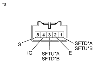
Text in Illustration *A for LHD *B for RHD *a Component without harness connected
(Transmission Control Switch)
Disconnect the N50*1 or T11*2 transmission control switch connector.
-
*1: for LHD
-
*2: for RHD
-
-
Measure the resistance according to the value(s) in the table below when the shift lever is moved to each position.
Standard Resistance for LHD Tester Connection Condition Specified Condition N50-4 (IG) - N50-5 (S) S, "+" and "-" Below 1 Ω N50-3 (SFTU) - N50-2 (E) Press continuously
"+"
(Up shift)
Below 1 Ω N50-1 (SFTD) - N50-2 (E) Press continuously
"-"
(Down shift)
Below 1 Ω N50-4 (IG) - N50-5 (S) Except S, "+" and "-" 10 kΩ or higher N50-3 (SFTU) - N50-2 (E) S 10 kΩ or higher N50-1 (SFTD) - N50-2 (E) S 10 kΩ or higher for RHD Tester Connection Condition Specified Condition T11-4 (IG) - T11-5 (S) S, "+" and "-" Below 1 Ω T11-1 (SFTU) - T11-2 (E) Press continuously
"+"
(Up shift)
Below 1 Ω T11-3 (SFTD) - T11-2 (E) Press continuously
"-"
(Down shift)
Below 1 Ω T11-4 (IG) - T11-5 (S) Except S, "+" and "-" 10 kΩ or higher T11-1 (SFTU) - T11-2 (E) S 10 kΩ or higher T11-3 (SFTD) - T11-2 (E) S 10 kΩ or higher -
Reconnect the N50*1 or T11*2 transmission control switch connector.
-
*1: for LHD
-
*2: for RHD
-
NG
REPLACE TRANSMISSION CONTROL SWITCH (TRANSMISSION FLOOR SHIFT ASSEMBLY) Click here
OK
-
-
CHECK HARNESS AND CONNECTOR (TRANSMISSION CONTROL SWITCH - POWER MANAGEMENT CONTROL ECU)
-
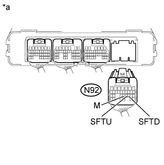
Text in Illustration *a Rear view of wire harness connector
(to Power Management Control ECU)
Disconnect the N92 power management control ECU connector.
-
Turn the power switch on (IG).
-
Measure the voltage according to the value(s) in the table below when the shift lever is moved to each position.
Standard Voltage Tester Connection Condition Specified Condition N92-22 (M) - Body ground Power switch on (IG)
S, "+" and "-"
11 to 14 V N92-22 (M) - Body ground Power switch on (IG)
Except S, "+" and "-"
Below 1 V Note
Turning the power switch on (IG) with the power management control ECU connector disconnected causes other DTCs to be stored. Clear the DTCs after performing this inspection.
-
Turn the power switch off.
-
Disconnect the N31 spiral cable sub-assembly connector.
-
Measure the resistance according to the value(s) in the table below when the shift lever is moved to each position.
Standard Resistance Tester Connection Condition Specified Condition N92-21 (SFTU) - Body ground Press continuously
"+"
(Up shift)
Below 1 Ω N92-20 (SFTD) - Body ground Press continuously
"-"
(Down shift)
Below 1 Ω N92-21 (SFTU) - Body ground S 10 kΩ or higher N92-20 (SFTD) - Body ground S 10 kΩ or higher -
Reconnect the N31 spiral cable sub-assembly connector.
-
Reconnect the N92 power management control ECU connector.
NG
REPAIR OR REPLACE HARNESS OR CONNECTOR
OK
REPLACE POWER MANAGEMENT CONTROL ECU Click here
-