IGNITION COIL AND SPARK PLUG INSTALLATION

Tech Tips
Perform "Inspection After Repairs" after replacing the ignition coil or the spark plug Click here.
-
INSTALL SPARK PLUG
-
Install the 6 spark plugs.
- Torque:
- 18 N*m { 184 kgf*cm, 13 ft.*lbf }
Note
If a component has been dropped or subjected to a strong impact, replace it.
Tech Tips
Perform "Inspection After Repairs" after replacing the spark plug Click here.
-
-
INSTALL IGNITION COIL ASSEMBLY
Tech Tips
Perform "Inspection After Repairs" after replacing the ignition coil Click here.
-
for Bank 1:
-
Install the 3 ignition coils with the 3 bolts.
- Torque:
- 10 N*m { 102 kgf*cm, 7 ft.*lbf }
Tech Tips
Perform "Inspection After Repairs" after replacing the ignition coil Click here.
-
Connect the VVT sensor connector and 3 ignition coil connectors to connect the engine wire.
-
Connect the clamp and install the 2 nuts.
- Torque:
- 10 N*m { 102 kgf*cm, 7 ft.*lbf }
-
-
for Bank 2:
-
Install the 3 ignition coils with the 3 bolts.
- Torque:
- 10 N*m { 102 kgf*cm, 7 ft.*lbf }
Tech Tips
Perform "Inspection After Repairs" after replacing the ignition coil Click here.
-
Connect the manifold absolute pressure sensor connector, VVT sensor connector and 3 ignition coil connectors to connect the engine wire.
-
Connect the 2 clamps and install the 3 nuts.
- Torque:
- 10 N*m { 102 kgf*cm, 7 ft.*lbf }
-
-
Connect the inverter reservoir tank assembly with the 2 bolts.
- Torque:
- 13 N*m { 133 kgf*cm, 10 ft.*lbf }
-
for RHD:
Install the inverter bracket to the inverter with the 2 bolts.
- Torque:
- 8.0 N*m { 82 kgf*cm, 71 in.*lbf }
-
for RHD:
Attach the 2 wire harness clamps to the inverter bracket.
-
-
INSTALL AIR CLEANER CAP WITH AIR CLEANER HOSE
-
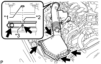
Text in Illustration *1 Bump *2 Cutout *3 Protrusion Install the air cleaner cap with air cleaner hose assembly with the 4 clamps and hose clamp.
- Torque:
- 4.0 N*m { 41 kgf*cm, 35 in.*lbf }
Note
-
Insert the protrusion on the throttle body side hose into the hole of the hose clamp.
-
Align the bump on the throttle body side with the cutout in the hose.
-
Connect the VSV hose to the air cleaner hose.
-
Connect the mass air flow meter connector and clamp to the air cleaner.
-
-
INSTALL NO. 2 VENTILATION HOSE
-
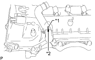
Text in Illustration *1 Rib *2 Paint Mark Align the paint mark of the No. 2 ventilation hose with the rib of the cylinder head cover RH and connect the hose.
-
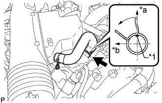
Text in Illustration *1 Paint Mark *a Top *b Front Connect the No. 2 ventilation hose to the cylinder head cover with the clamp.
Tech Tips
Make sure the direction of the clip is as shown in the illustration.
-
-
INSTALL COOL AIR INTAKE DUCT SEAL
-
Install the cool air intake duct seal with the 7 clips.
-
-
INSTALL ENGINE ROOM SIDE COVER
-
Install the engine room side cover with the 4 clips.
-
-
INSTALL V-BANK COVER SUB-ASSEMBLY
-
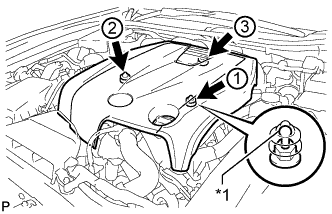
Text in Illustration *1 Tip (Round Portion) Attach the 3 clips in the order shown in the illustration to install the V-bank cover.
Note
-
Securely attach the clips.
-
If the clips are forcibly attached or struck with an object, they may be damaged.
-
Do not apply any oil to the tips (round portions).
-
-