TOE CONTROL LINK INSTALLATION

-
TEMPORARILY INSTALL TOE CONTROL LINK SUB-ASSEMBLY
-
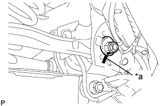
Text in Illustration *a Matchmark Install the toe control link and insert the toe adjust cam from the front of the vehicle. Then install the No. 2 toe adjust plate and temporarily install the nut.
Note
Align the matchmarks on the rear suspension member and rear No. 2 suspension toe adjust plate.
-
Install the rear suspension toe control link with a new nut.
- Torque:
- 70 N*m { 714 kgf*cm, 52 ft.*lbf }
-
-
STABILIZE SUSPENSION
-
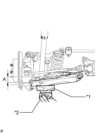
Text in Illustration *1 Wooden Block *2 Jack Jack up the rear No. 2 suspension arm assembly, and place a wooden block underneath to avoid damage. Apply load to the suspension so that the rear No. 2 suspension arm assembly is positioned as shown in the illustration.
Standard Length (A) 9.7 mm (0.3819 in.) Note
-
When jacking up the rear No. 2 suspension arm assembly, be sure to jack it up slowly.
-
Do not jack up the rear No. 2 suspension arm assembly too high as the vehicle may fall.
-
Make sure to perform this operation with the vehicle kept as low as possible.
-
-
-
TIGHTEN TOE CONTROL LINK SUB-ASSEMBLY
-
Tighten the nut on the rear suspension member side.
- Torque:
- 117 N*m { 1193 kgf*cm, 86 ft.*lbf }
Note
Check that the matchmarks on the rear suspension member and rear No. 2 suspension toe adjust plate are aligned.
-
-
INSTALL REAR WHEEL
- Torque:
- 103 N*m { 1050 kgf*cm, 76 ft.*lbf }
-
INSPECT AND ADJUST REAR WHEEL ALIGNMENT