REAR LOWER ARM INSTALLATION

-
TEMPORARILY INSTALL REAR NO. 2 SUSPENSION ARM ASSEMBLY
-
Temporarily install the rear No. 2 suspension arm assembly to the rear suspension member with the bolt, nut and washer.
Note
Insert the bolt with the threaded end facing the front of the vehicle.
-
Install the rear lower coil spring insulator to the rear No. 2 suspension arm.
-
Install the rear upper coil spring insulator to the rear coil spring.
-
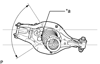
Text in Illustration *a Identification Mark Temporarily install the rear coil spring to the rear No. 2 suspension arm.
Note
Make sure that the identification mark is positioned towards the lower and outer sides of the vehicle.
-
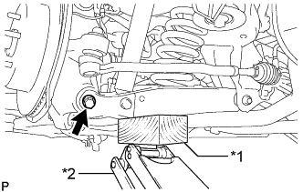
Text in Illustration *1 Wooden Block *2 Jack Using a jack and wooden block, raise the vehicle gradually to install the rear No. 2 suspension arm to the rear axle carrier. Then temporarily install the bolt and nut.
Note
-
Insert the bolt with the threaded end facing the rear of the vehicle.
-
When jacking up the rear No. 2 suspension arm assembly, be sure to jack it up slowly.
-
Do not jack up the rear No. 2 suspension arm assembly too high as the vehicle may fall.
-
Make sure to perform this operation with the vehicle kept as low as possible.
-
-
-
INSTALL REAR SUSPENSION MEMBER BRACE
-
Install the rear suspension member brace with the 2 new bolts.
- Torque:
- 56 N*m { 571 kgf*cm, 41 ft.*lbf }
-
-
TEMPORARILY INSTALL REAR SHOCK ABSORBER ASSEMBLY
-
Temporarily install the rear shock absorber assembly to the rear No. 2 suspension arm with the bolt and nut.
Note
Insert the bolt with the threaded end facing the rear of the vehicle.
-
-
INSTALL REAR STABILIZER LINK ASSEMBLY
-
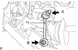
Text in Illustration *1 Identification Mark Install the rear stabilizer link assembly with the 2 nuts.
- Torque:
- for nut A
- 89 N*m { 908 kgf*cm, 66 ft.*lbf }
- for nut B
- 70 N*m { 714 kgf*cm, 52 ft.*lbf }
Note
The identification mark must be facing towards the top of the vehicle when installing the rear stabilizer link.
Tech Tips
If the ball joint turns together with the nut, use a 6 mm hexagon wrench to hold the stud bolt.
-
-
TEMPORARILY INSTALL REAR NO. 1 SUSPENSION ARM ASSEMBLY
-
Temporarily install the rear No. 1 suspension arm assembly to the rear suspension member with the bolt and nut.
Note
Insert the bolt with the threaded end facing the rear of the vehicle.
-
Temporarily install the rear No. 1 suspension arm assembly to the axle carrier with the bolt and nut.
Note
Insert the bolt with the threaded end facing the rear of the vehicle.
-
-
CONNECT TOE CONTROL LINK SUB-ASSEMBLY (w/o DYNAMIC REAR STEERING)
-
Connect the toe control link sub-assembly to the rear axle assembly with a new nut.
- Torque:
- 70 N*m { 714 kgf*cm, 52 ft.*lbf }
-
-
CONNECT REAR STEERING LINK ASSEMBLY (w/ DYNAMIC REAR STEERING)
-
Connect the rear steering link assembly to the rear axle assembly with a new nut.
- Torque:
- 70 N*m { 714 kgf*cm, 52 ft.*lbf }
-
-
STABILIZE SUSPENSION
-
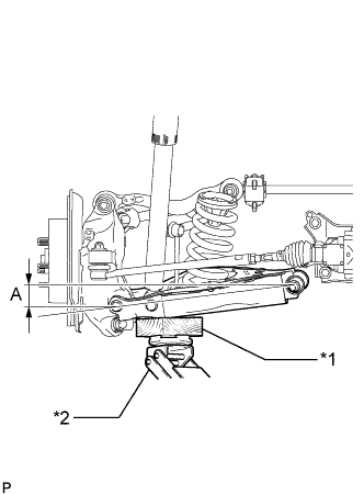
Text in Illustration *1 Wooden Block *2 Jack Jack up the rear No. 2 suspension arm assembly, and place a wooden block underneath to avoid damage. Apply load to the suspension so that the rear No. 2 suspension arm assembly is positioned as shown in the illustration.
Standard Length (A) 9.7 mm (0.3819 in.) Note
-
When jacking up the rear No. 2 suspension arm assembly, be sure to jack it up slowly.
-
Do not jack up the rear No. 2 suspension arm assembly too high as the vehicle may fall.
-
Make sure to perform this operation with the vehicle kept as low as possible.
-
-
-
TIGHTEN REAR SHOCK ABSORBER ASSEMBLY
-
Tighten the bolt of the rear shock absorber.
- Torque:
- 110 N*m { 1122 kgf*cm, 81 ft.*lbf }
Note
Since a stopper nut is used, tighten the bolt.
-
-
TIGHTEN REAR NO. 1 SUSPENSION ARM ASSEMBLY
-
Tighten the nut of the rear No. 1 suspension arm assembly for the suspension member side.
- Torque:
- 90 N*m { 918 kgf*cm, 66 ft.*lbf }
-
Tighten the bolt of the rear No. 2 suspension arm assembly for the rear axle assembly side.
- Torque:
- 90 N*m { 918 kgf*cm, 66 ft.*lbf }
-
-
TIGHTEN REAR NO. 2 SUSPENSION ARM ASSEMBLY
-
Tighten the nut of the rear No. 2 suspension arm assembly for the suspension member side.
- Torque:
- 150 N*m { 1530 kgf*cm, 111 ft.*lbf }
-
Tighten the bolt of the rear No. 2 suspension arm assembly for the rear axle assembly side.
- Torque:
- 145 N*m { 1479 kgf*cm, 107 ft.*lbf }
-
-
INSTALL REAR SUSPENSION ARM COVER
-
Install the rear suspension arm cover to the rear No. 2 suspension arm with the 3 bolts.
- Torque:
- 12 N*m { 122 kgf*cm, 9.0 ft.*lbf }
-
-
CONNECT REAR HEIGHT CONTROL SENSOR SUB-ASSEMBLY
-
Connect the rear height control sensor to the rear No. 1 upper control arm with the nut.
- Torque:
- 8.0 N*m { 82 kgf*cm, 71 in.*lbf }
-
-
INSTALL REAR WHEEL
- Torque:
- 103 N*m { 1050 kgf*cm, 76 ft.*lbf }
-
INSPECT AND ADJUST REAR WHEEL ALIGNMENT
-
HEADLIGHT AIMING ADJUSTMENT
-
for HID Headlight:
-
for LED Headlight:
-