REAR UPPER ARM REMOVAL

-
REMOVE REAR WHEEL
-
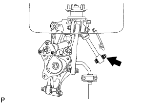
DISCONNECT REAR HEIGHT CONTROL SENSOR SUB-ASSEMBLY
-
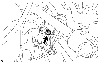
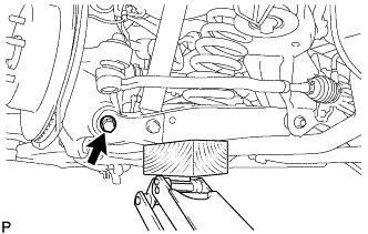
Remove the nut and disconnect the rear height control sensor from the rear No. 1 upper control arm.
-
-
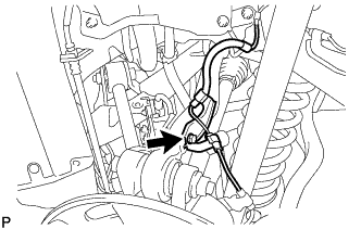
DISCONNECT REAR SPEED SENSOR
-
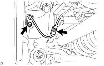
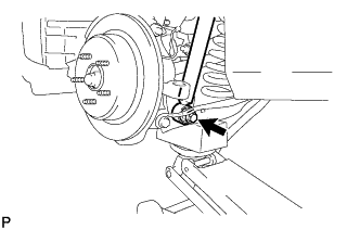
Remove the 2 bolts and disconnect the rear speed sensor from the rear axle assembly.
-
-
REMOVE REAR AXLE SHAFT NUT
-
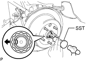
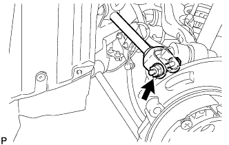
Using SST and a hammer, release the staked part of the axle shaft nut.
- SST
- 09930-00010
Note
Release the staked part of the nut completely, otherwise the screw of the drive shaft may be damaged.
-
While applying the brakes, remove the rear axle shaft nut.
-
-
REMOVE PARKING BRAKE
-
REMOVE REAR SUSPENSION ARM COVER
-
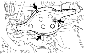
Remove the 3 bolts and rear suspension arm cover from the rear No. 2 suspension arm assembly.
-
-
DISCONNECT TOE CONTROL LINK SUB-ASSEMBLY (w/o DYNAMIC REAR STEERING)
-
Remove the nut.
-
Install 2 spacers (SST spacer B) to the toe control link so that there is a space of approximately 1 mm (0.0394 in.) between the link and spacers.
- SST
- 09960-20010 ( 09961-02060 )
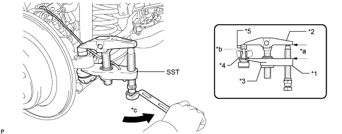
Text in Illustration *1 Claw *2 Body *3 Nut *4 Spacer *5 SST (Spacer B) - - *a Parallel *b Space of approx. 1 mm *c Turn - - Note
-
Make sure to install the spacers (SST spacer B) as the axle carrier spacer may shift.
-
As SST may become damaged, make sure the space between the arm and spacers is not less than 1 mm (0.0394 in.).
-
Using SST, disconnect the toe control link from the rear axle assembly.
- SST
- 09960-20010 ( 09961-02010 )
CAUTION:
Apply grease molybdenum grease to the threads and end of the SST bolt.
Note
-
Do not damage the dust cover.
-
As the dust cover may be damaged, adjust SST with the center nut so that the body and claw are parallel.
-
Make sure to tie the string of SST to the vehicle to prevent SST from dropping.
-
-
DISCONNECT REAR STEERING LINK ASSEMBLY (w/ DYNAMIC REAR STEERING)
-
Remove the nut.
-
Install 2 spacers (SST spacer B) to the rear steering link so that there is a space of approximately 1 mm (0.0394 in.) between the link and spacers.
- SST
- 09960-20010 ( 09961-02060 )
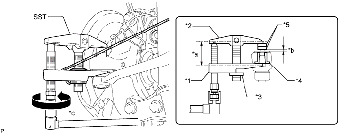
Text in Illustration *1 Claw *2 Body *3 Nut *4 Spacer *5 SST (Spacer B) - - *a Parallel *b Space of approx. 1 mm *c Turn - - Note
-
Make sure to install the spacers (SST spacer B) as the axle carrier spacer may shift.
-
As SST may become damaged, make sure the space between the arm and spacers is not less than 1 mm (0.0394 in.).
-
Using SST, disconnect the rear steering link from the rear axle assembly.
- SST
- 09960-20010 ( 09961-02010 )
CAUTION:
Apply grease molybdenum grease to the threads and end of the SST bolt.
Note
-
Do not damage the dust cover.
-
As the dust cover may be damaged, adjust SST with the center nut so that the body and claw are parallel.
-
Make sure to tie the string of SST to the vehicle to prevent SST from dropping.
-
-
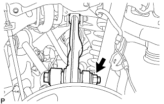
DISCONNECT REAR NO. 1 SUSPENSION ARM ASSEMBLY
-
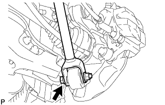
Remove the bolt and nut, and disconnect the rear No. 1 suspension arm assembly from the rear axle assembly.
-
-
REMOVE REAR STABILIZER LINK ASSEMBLY
-
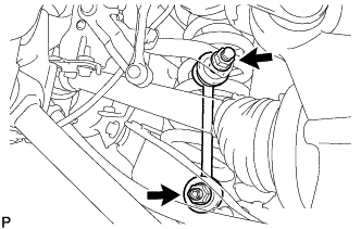
Remove the 2 nuts and rear stabilizer link assembly.
Tech Tips
If the ball joint turns together with the nut, use a 6 mm hexagon wrench to hold the stud bolt.
-
-
DISCONNECT REAR SHOCK ABSORBER ASSEMBLY
-
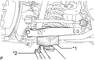
Using a jack and wooden block, jack up the rear No. 2 suspension arm assembly.
Note
-
When jacking up the rear No. 2 suspension arm assembly, be sure to jack it up slowly.
-
Do not jack up the rear No. 2 suspension arm assembly too high as the vehicle may fall.
-
Make sure to perform this operation with the vehicle kept as low as possible.
-
-
Remove the bolt and nut, and disconnect the rear shock absorber from the rear No. 2 suspension arm assembly.
Note
Hold the nut and remove the bolt.
-
-
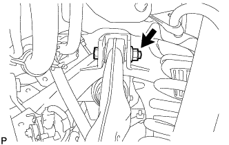
DISCONNECT REAR NO. 2 SUSPENSION ARM ASSEMBLY
-
Loosen the bolt and nut of the rear No. 2 suspension arm on the rear suspension member side.
-
Remove the bolt and nut located on the rear axle assembly of the rear No. 2 suspension arm.
Note
Hold the nut and remove the bolt.
-
Lower the jack gradually to remove the rear coil spring with rear upper coil spring insulator.
-
Remove the rear lower coil spring insulator from the rear No. 2 suspension arm.
-
-
REMOVE REAR NO. 1 UPPER CONTROL ARM ASSEMBLY
-
Remove the bolt, nut and washer, and disconnect the rear No. 1 upper control arm assembly from the rear axle assembly.
-
Remove the bolt, nut, washer and rear No. 1 upper control arm assembly from the rear suspension member.
-
-
REMOVE REAR UPPER CONTROL ARM ASSEMBLY
-
Remove the bolt and disconnect the rear speed sensor from the rear upper control arm.
-
Remove the bolt, nut and washer, and disconnect the rear upper control arm assembly from the rear axle assembly.
-
Remove the bolt, nut, washer and rear upper control arm assembly from the rear suspension member.
-