FRONT SUSPENSION MEMBER INSTALLATION

-
TEMPORARILY INSTALL FRONT SUSPENSION LOWER ARM ASSEMBLY LH
-
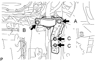
Install the front suspension lower arm and side rail plate with the 4 bolts.
- Torque:
- for bolt A
- 194 N*m { 1978 kgf*cm, 143 ft.*lbf }
- for bolt B
- 86 N*m { 877 kgf*cm, 63 ft.*lbf }
- for bolt C
- 50 N*m { 510 kgf*cm, 37 ft.*lbf }
-
Temporarily tighten the bolt, washer and nut.
-
Install the front lower ball joint with the 2 bolts.
- Torque:
- 150 N*m { 1530 kgf*cm, 111 ft.*lbf }
-
-
TEMPORARILY INSTALL FRONT SUSPENSION LOWER ARM ASSEMBLY RH
Tech Tips
Use the same procedure described for the LH side.
-
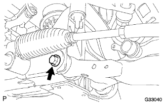
INSTALL POWER STEERING LINK ASSEMBLY
-
Install the power steering link assembly with the 2 bolts, 2 washers, and 2 nuts.
- Torque:
- 118 N*m { 1199 kgf*cm, 87 ft.*lbf }
-
Connect the wire harness connectors to the power steering link assembly.
-
-
INSTALL FRONT STABILIZER BAR
-
Install the front stabilizer bar.
-
-
INSTALL FRONT STABILIZER LINK ASSEMBLY LH
-
Install the front stabilizer link assembly LH with the 2 nuts.
- Torque:
- 84 N*m { 857 kgf*cm, 62 ft.*lbf }
Tech Tips
If the ball joint turns together with the nut, use a 6 mm hexagon wrench to hold the stud.
-
-
INSTALL FRONT STABILIZER LINK ASSEMBLY RH
Tech Tips
Use the same procedure described for the LH side.
-
INSTALL FRONT SUSPENSION CROSSMEMBER SUB-ASSEMBLY
-
Install the front suspension crossmember sub-assembly with the 2 bolts.
- Torque:
- 35 N*m { 357 kgf*cm, 26 ft.*lbf }
-
-
INSTALL ENGINE AND TRANSMISSION ASSEMBLY
-
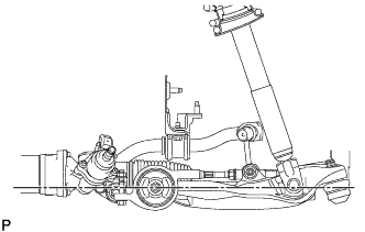
STABILIZE SUSPENSION
-
Install the front wheels.
- Torque:
- 103 N*m { 1050 kgf*cm, 76 ft.*lbf }
-
Lower the vehicle and bounce it up and down several times to stabilize the front suspension.
-
Remove the front wheels.
-
Jack up the front suspension lower arm placing a wooden block in between. Apply a load to the front suspension so that the front suspension lower arm is placed in a horizontal position.
-
-
TIGHTEN FRONT SUSPENSION LOWER ARM ASSEMBLY LH
-
Fully tighten the bolt on the front of the front suspension lower arm.
- Torque:
- 135 N*m { 1377 kgf*cm, 100 ft.*lbf }
-
Fully tighten the installation nut of the lower arm No. 2 bracket sub-assembly.
- Torque:
- 113 N*m { 1152 kgf*cm, 83 ft.*lbf }
-
-
TIGHTEN FRONT SUSPENSION LOWER ARM ASSEMBLY RH
Tech Tips
Use the same procedure described for the LH side.