STEERING KNUCKLE INSTALLATION

-
INSTALL STEERING KNUCKLE
-
Install the steering knuckle to the upper suspension arm with a castle nut and new clip.
- Torque:
- 87 N*m { 887 kgf*cm, 64 ft.*lbf }
Note
If the holes for the clip are not aligned, tighten the nut up to another 60°.
-
-
INSTALL FRONT AXLE HUB SUB-ASSEMBLY
-
Install the front axle hub sub-assembly with the 4 bolts.
- Torque:
- 69 N*m { 704 kgf*cm, 51 ft.*lbf }
-
-
INSTALL FRONT LOWER BALL JOINT ASSEMBLY
-
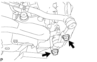
Install the steering knuckle to the lower ball joint with the 2 bolts.
- Torque:
- 150 N*m { 1530 kgf*cm, 111 ft.*lbf }
-
-
INSTALL FRONT DISC BRAKE CALIPER ASSEMBLY
-
Connect the front disc brake caliper assembly to the steering knuckle with the 2 bolts.
- Torque:
- 135 N*m { 1377 kgf*cm, 100 ft.*lbf }
Note
-
Do not twist the front brake hose when installing the front disc brake caliper.
-
Make sure that there are no foreign objects or damage to the threads of the bolts.
-
Do not overtighten the bolts because the steering knuckle is made of aluminum and may be damaged.
-
-
INSTALL SPEED SENSOR CONNECTOR
-
Connect the speed sensor connector to the front speed sensor.
Note
Do not twist the sensor wire.
-
-
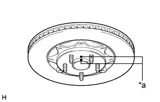
INSTALL FRONT DISC (for 17 inch Front Disc Brake)
Note
The front disc has an identification mark. Check the identification mark when installing the disc.
-
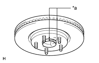
Text in Illustration *a Matchmark Align the matchmarks and install the front disc.
Tech Tips
When replacing the front disc with a new one, select the installation position where the front disc has the smallest runout.
-
-
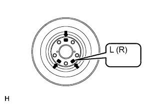
INSTALL FRONT DISC (for 18 inch Front Disc Brake)
Note
-
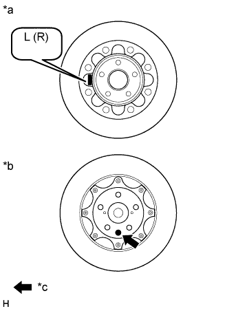
The front disc needs to be installed to the correct side of the vehicle. There is an "L", indicating the disc for the left wheel, or an "R", indicating the disc for the right wheel, engraved on the inside of the disc in the position shown in the illustration.
-
There is pink paint, indicating the disc for the left wheel, or green paint, indicating the disc for the right wheel, on the surface of the front disc in the position shown in the illustration.
Text in Illustration *a Inner Disc *b Outer Disc *c Disc Identification Paint
-
Text in Illustration *a Matchmark Align the matchmarks and install the front disc.
Tech Tips
When replacing the front disc with a new one, select the installation position where the front disc has the smallest runout.
-
-
INSTALL FRONT WHEEL
- Torque:
- 103 N*m { 1050 kgf*cm, 76 ft.*lbf }
-
INSPECT AND ADJUST FRONT WHEEL ALIGNMENT
-
CHECK ABS SPEED SENSOR SIGNAL