SHIFT LEVER POSITION SENSOR INSTALLATION

-
INSTALL SHIFT LEVER POSITION SENSOR
-
Install the shift lever position sensor to the hybrid vehicle transmission assembly.
Tech Tips
Make sure that the manual valve lever shaft has not been rotated prior to installing the park/neutral position switch as the detent spring may become detached from the manual valve lever shaft.
-
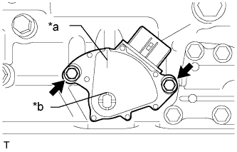
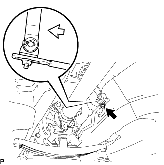
Text in Illustration *a Neutral Alignment Mark Line *b Groove Temporarily install the 2 bolts.
Tech Tips
Tighten the bolts with the neutral alignment mark line aligned with the groove. [*1]
-
Install a lock washer and the nut.
- Torque:
- 6.9 N*m { 70 kgf*cm, 61 in.*lbf }
-
Temporarily install the control shaft lever.
Tech Tips
Stake the claws of the nut stopper before fully tightening the nut. [*2]
-
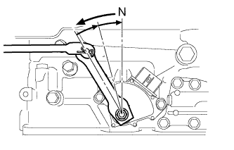
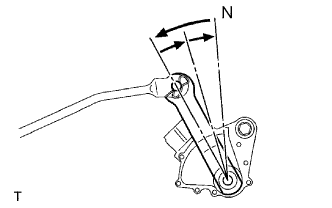
Turn the control shaft lever counterclockwise until it stops. Next, turn the control shaft lever clockwise 2 notches to set it to N.
-
Remove the transmission control shaft lever.
-
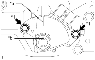
Text in Illustration *1 Adjusting Bolt *a Neutral Alignment Mark Line *b Groove Align the neutral alignment mark line with the switch groove, and tighten the 2 adjusting bolts. [*1]
- Torque:
- 5.4 N*m { 55 kgf*cm, 48 in.*lbf }
-
Using a screwdriver, bend the lock washer tabs to secure the nut.
Note
Make sure that the nut is held firmly.
-
Install the transmission control shaft lever with the nut. [*2]
- Torque:
- 16 N*m { 160 kgf*cm, 12 ft.*lbf }
-
Connect the shift lever position sensor connector.
-
-
INSTALL REAR ENGINE MOUNTING MEMBER
-
Tilt up the hybrid vehicle transmission assembly.
-
Install the rear engine mounting member to the body with the 4 bolts.
- Torque:
- 35 N*m { 354 kgf*cm, 26 ft.*lbf }
-
-
CONNECT FLOOR SHIFT GEAR SHIFTING ROD SUB-ASSEMBLY
-
Turn the transmission control shaft lever RH of the park/neutral position switch assembly counterclockwise until it stops, and then turn it clockwise 2 notches to set it to N.
-
Move the shift lever to N and tighten the nut while lightly pushing the lever toward R.
Text in Illustration 
Push Note
Do not push the shift lever too hard.
-
After adjustment, check that the shift lever moves smoothly and the shift lever and gear operate correctly.
-
Connect the floor shift gear shifting rod sub-assembly with the nut.
- Torque:
- 13 N*m { 130 kgf*cm, 9 ft.*lbf }
-
-
INSTALL PROPELLER WITH CENTER BEARING SHAFT ASSEMBLY
-
INSTALL INTAKE AIR SURGE TANK ASSEMBLY
-
INSPECT SHIFT LEVER POSITION
-
Apply the parking brake.
-
Lock the wheels with chocks to secure the vehicle.
-
Turn the power switch on (READY).
-
Move the shift lever to D and release the brake pedal.
Note
Be sure to apply the parking brake and lock the wheels with chocks to secure the vehicle.
-
Slowly move the shift lever to N and measure the moving distance (A) of the shift lever from the original point to the gear activation point.
Note
Be sure to move the shift lever slowly.
-
Move the shift lever to R and release the brake pedal.
Note
Be sure to apply the parking brake and lock the wheels with chocks to secure the vehicle.
-
Slowly move the shift lever to N and measure the moving distance (B) of the shift lever from the original point to the vehicle activation point.
Note
Be sure to move the shift lever slowly.
-
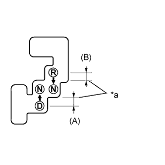
Text in Illustration *a Gear Activation Point Check that moving distances (A) and (B) shown in the illustration are almost the same.
Tech Tips
-
If moving distances (A) and (B) are almost the same, adjustment of the shift lever position is not necessary.
-
If moving distance (A) is shorter than (B), perform adjustment of the shift lever position [*1].
-
If moving distance (B) is shorter than (A), perform adjustment of the shift lever position [*2].
-
-
-
ADJUST SHIFT LEVER POSITION
-

If moving distance (A) is shorter than (B) [*1]:
Text in Illustration *a Gear Activation Point 
Clockwise Tech Tips
If the shift lever is moved from R to N, the moving distance of the shift lever from the original point to the gear activation point becomes longer.
-
Move the shift lever to N.
-
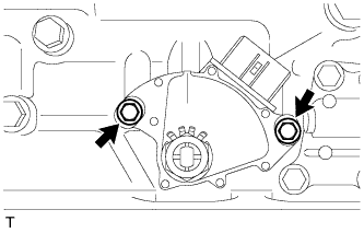
Loosen the 2 bolts.
-
Slightly turn the shift lever position sensor clockwise.
-
Tighten the shift lever position sensor with the 2 bolts.
- Torque:
- 5.4 N*m { 55 kgf*cm, 48 in.*lbf }
-
Recheck the shift lever position.
-
-
If moving distance (B) is shorter than (A) [*2]:
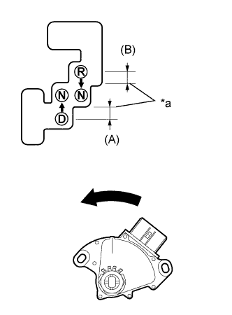
Text in Illustration *a Gear Activation Point Counterclockwise Tech Tips
If the shift lever is moved from D to N, the moving distance of the shift lever from the original point to the gear activation point becomes longer.
-
Move the shift lever to N.
-
Loosen the 2 bolts.
-
Slightly turn the shift lever position sensor counterclockwise.
-
Tighten the shift lever position sensor with the 2 bolts.
- Torque:
- 5.4 N*m { 55 kgf*cm, 48 in.*lbf }
-
Recheck the shift lever position.
-
-
-
INSPECT SHIFT LEVER OPERATION
-
While moving the shift lever from N to each position, check that the lever moves smoothly and that the shift position indicator comes on properly according to the shift lever position.
-
Turn the power switch on (READY) and check the following:
-
When the shift lever is moved to D, the vehicle moves forward.
-
When the shift lever is moved to R, the buzzer sounds and the vehicle moves in reverse.
Note
The vehicle should not move when the shift position indicator is off.
-
-
-
INSTALL NO. 2 ENGINE UNDER COVER
-
Install the No. 2 engine under cover with the 4 screws and 2 grommets.
-
-
INSTALL FRONT SUSPENSION MEMBER BRACE
-
Install the front suspension member brace with the clip and 4 bolts.
- Torque:
- 52 N*m { 530 kgf*cm, 38 ft.*lbf }
-