TRANSMISSION WIRE INSTALLATION

-
INSTALL TRANSMISSION WIRE
-
Coat the O-ring on the transmission wire with ATF.
-
Install the transmission wire.
-
Using a 10 mm union nut wrench, tighten the bolt.
- Torque:
- 5.4 N*m { 55 kgf*cm, 48 in.*lbf }
Note
Use the formula to calculate special torque values for situations where a union nut wrench is combined with a torque wrench Click here.
-
Connect the transmission wire connector.
-
Connect the 3 connectors to the solenoid valves.
-
Connect the 2 oil pressure switch connectors.
Note
Make sure that the terminals are securely engaged with the oil pressure switches.
Tech Tips
If the terminals do not engage securely, replace the transmission wire.
-
Coat a new O-ring with ATF and install it to the ATF temperature sensor.
-
Install the ATF temperature sensor and lock plate with the bolt.
- Torque:
- 6.6 N*m { 67 kgf*cm, 58 in.*lbf }
-
Install the wire harness clamp with the bolt.
- Torque:
- 11 N*m { 110 kgf*cm, 8 ft.*lbf }
-
-
INSTALL OIL STRAINER ASSEMBLY
-
Coat a new O-ring with ATF and install it to the oil strainer.
-
Install the oil strainer to the valve body with the 3 bolts.
- Torque:
- 10 N*m { 102 kgf*cm, 7 ft.*lbf }
Note
-
When installing the oil strainer, do not allow the wire harness to get caught between the parts.
-
When installing the oil strainer, make sure that the O-ring is not twisted.
-
Do not allow the O-ring to get jammed between the parts.
Tech Tips
-
If a new oil strainer assembly is reinstalled, repeat turning the power switch off and on twice. DTCs for the oil pressure switch system may be output while performing this procedure, but they do not indicate malfunctions. Therefore, clear the DTCs.
-
After the oil strainer is replaced with a new one, enter the following menus: Powertrain / HV / Utility / B1 Air Bleeding.
-
-
INSTALL TRANSMISSION OIL PAN SUB-ASSEMBLY
-
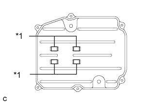
Text in Illustration *1 Magnet Install the 4 magnets to the oil pan sub-assembly.
-
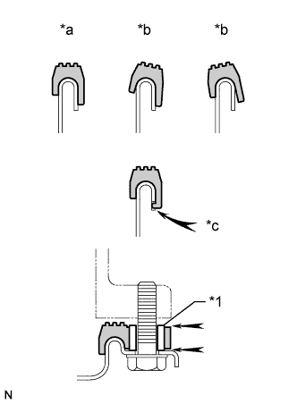
Text in Illustration *1 Sleeve *a Correct *b Incorrect *c Protrusion Install a new gasket to the oil pan.
Note
-
Make sure that there is no oil or foreign matter on the gasket seal surface or oil pan contact surface.
-
Install the gasket so that there is no slack in the gasket, and that the entire circumference of the seal surface is level.
-
Make sure that the 6 gasket drop prevention protrusions are set on the oil pan.
-
When tightening the oil pan, make sure that the gasket is not pinched between the gasket tightening area sleeve and the transmission seal surface.
-
-
Install the oil pan to the transmission case with the 6 bolts.
- Torque:
- 7.5 N*m { 76 kgf*cm, 66 in.*lbf }
-
-
ADD TRANSMISSION FLUID
-
INSTALL NO. 2 ENGINE UNDER COVER
-
Install the No. 2 engine under cover with the 4 screws and 2 grommets.
-
-
INSTALL FRONT SUSPENSION MEMBER BRACE
-
Install the front suspension member brace with the clip and 4 bolts.
- Torque:
- 52 N*m { 530 kgf*cm, 38 ft.*lbf }
-