OIL PUMP MOTOR CONTROLLER INSTALLATION

CAUTION:
Be sure to perform the procedure as described below. Do not turn the power switch on (READY) before the cable is connected to the negative battery terminal.
-
INSTALL OIL PUMP MOTOR CONTROLLER
-
Install the 2 oil pump motor controller brackets with the 3 bolts.
- Torque:
- 6.0 N*m { 61 kgf*cm, 53 in.*lbf }
-
Install the oil pump motor controller with bracket with the 2 bolts.
- Torque:
- 8.4 N*m { 86 kgf*cm, 74 in.*lbf }
-
-
CONNECT WIRE HARNESS
-
Connect the clamp.
-
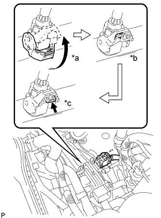
*a Raise the lever *b Lock the claw *c Push in the lock Connect the connector and securely lock the lock lever as shown in the illustration.
Note
-
Be sure to securely lock the claw of the connector.
-
Push the connector all the way in and lock the lock lever.
Tech Tips
When the connector is pushed all the way in, the lock lever will move slightly towards the lock position.
-
-
Push the lock into the lock lever to securely lock the lock lever of the connector.
-
Connect the connector to the oil pump motor controller.
-
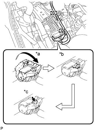
*a Raise the lever *b Lock the claw *c Push in the lock Connect the connector and securely lock the lock lever as shown in the illustration.
Note
-
Be sure to securely lock the claw of the connector.
-
Push the connector all the way in and lock the lock lever.
Tech Tips
When the connector is pushed all the way in, the lock lever will move slightly towards the lock position.
-
-
Install the clamp to the bracket.
-
Push the lock into the lock lever to securely lock the lock lever of the connector.
-
-
INSTALL AIR CLEANER CASE
-
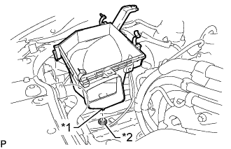
Text in Illustration *1 Pin *2 Grommet Insert the pin on the lower side of the air cleaner case into the grommet.
-
Install the air cleaner case, 2 clamps and 2 bolts.
- Torque:
- 5.0 N*m { 51 kgf*cm, 44 in.*lbf }
Note
During removal, do not lose the grommet on the underside of the air cleaner case.
-
-
INSTALL AIR CLEANER FILTER ELEMENT SUB-ASSEMBLY
-
INSTALL AIR CLEANER CAP WITH AIR CLEANER HOSE
-
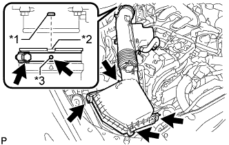
Text in Illustration *1 Bump *2 Cutout *3 Protrusion Install the air cleaner cap with air cleaner hose assembly with the 4 clamps and hose clamp.
- Torque:
- 4.0 N*m { 41 kgf*cm, 35 in.*lbf }
Note
-
Insert the protrusion on the throttle body side hose into the hole of the hose clamp.
-
Align the bump on the throttle body side with the cutout in the hose.
-
Connect the VSV hose to the air cleaner hose.
-
Connect the mass air flow meter connector and clamp to the air cleaner.
-
-
CONNECT NO. 2 VENTILATION HOSE
-
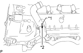
Text in Illustration *1 Rib *2 Paint Mark Align the paint mark of the No. 2 ventilation hose with the rib of the cylinder head cover RH and connect the hose.
-
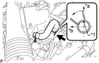
Text in Illustration *1 Paint Mark *a Top *b Front Connect the No. 2 ventilation hose to the cylinder head cover with the clamp.
Tech Tips
Make sure the direction of the clip is as shown in the illustration.
-
-
INSTALL NO. 1 AIR CLEANER INLET
-
Install the No. 1 air cleaner inlet with the bolt.
- Torque:
- 5.0 N*m { 51 kgf*cm, 44 in.*lbf }
-
-
CONNECT CABLE TO NEGATIVE BATTERY TERMINAL
Note
When disconnecting the cable, some systems need to be initialized after the cable is reconnected Click here.
-
INSTALL V-BANK COVER SUB-ASSEMBLY
-
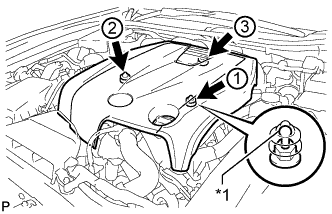
Text in Illustration *1 Tip (Round Portion) Attach the 3 clips in the order shown in the illustration to install the V-bank cover.
Note
-
Securely attach the clips.
-
If the clips are forcibly attached or struck with an object, they may be damaged.
-
Do not apply any oil to the tips (round portions).
-
-
-
INSTALL COOL AIR INTAKE DUCT SEAL
-
Install the cool air intake duct seal with the 7 clips.
-
-
INSTALL ENGINE ROOM SIDE COVER
-
Install the engine room side cover with the 4 clips.
-
-
INSTALL LUGGAGE COMPARTMENT TRIM COVER LH
-
Install the luggage compartment trim cover LH.
-
-
INSTALL LUGGAGE COMPARTMENT FLOOR MAT
-
Install the luggage compartment floor mat.
-