OIL PUMP INSTALLATION

-
INSTALL OIL WITH MOTOR PUMP ASSEMBLY
-
Install a new gasket to the oil with motor pump assembly.
-
Using SST, install the oil with motor pump assembly with the 4 bolts.
- SST
- 09961-01270
- Torque:
- without SST
- 32 N*m { 321 kgf*cm, 23 ft.*lbf }
- with SST
- 15 N*m { 152 kgf*cm, 11 ft.*lbf }
Tech Tips
-
Use a torque wrench with a fulcrum length of 180 mm (7.09 in.). When using a torque wrench with a fulcrum length that is not 180 mm (7.09 in.), calculate the torque specification for the torque wrench and SST based on the "without SST" torque specification Click here.
-
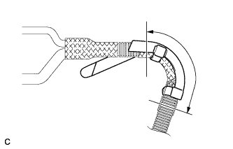
Make sure SST and the wrench are connected in a straight line.
-
Connect the transmission breather hose.
-
-
INSTALL OIL COOLER UNION SUB-ASSEMBLY
-
Position the oil cooler union sub-assembly and 4 new gaskets by temporarily tightening the 2 union bolts and the bolt.
-
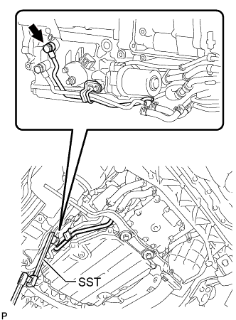
Using SST, tighten the union bolt.
- SST
- 09961-00950
- Torque:
- without SST
- 28 N*m { 280 kgf*cm, 20 ft.*lbf }
- with SST
- 15 N*m { 153 kgf*cm, 11 ft.*lbf }
Tech Tips
-
Use a torque wrench with a fulcrum length of 180 mm (7.09 in.). When using a torque wrench with a fulcrum length that is not 180 mm (7.09 in.), calculate the torque specification for the torque wrench and SST based on the "without SST" torque specification Click here.
-
Make sure SST and the wrench are connected in a straight line.
-
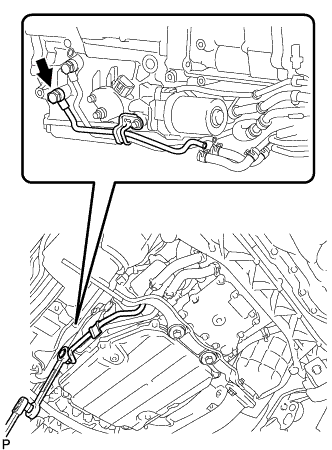
Using a 19 mm ball joint lock nut wrench, tighten the union bolt.
- Torque:
- 28 N*m { 280 kgf*cm, 20 ft.*lbf }
Note
Use the formula to calculate special torque values for situations where a union nut wrench is combined with a torque wrench Click here.
-
Tighten the bolt to install the oil cooler union sub-assembly.
- Torque:
- 12 N*m { 122 kgf*cm, 9 ft.*lbf }
-
Connect the 2 oil cooler hoses.
-
-
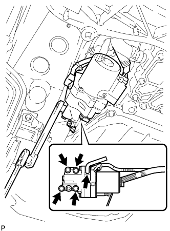
CONNECT WIRE HARNESS
-
Install the 9 wire harness clamps and 2 connectors to the hybrid vehicle transmission assembly.
-
-
INSTALL WIRING HARNESS PROTECTOR
-
Install a new wiring harness protector to the harness.
Note
-
Securely install the 2 locks.
-
Be sure to install the wire harness protector in the location of the matchmarks placed during removal.
-
-
Using tape or equivalent, cover the area indicated in the illustration.
-
Insert the claw of a new wire harness protector into the hole in the side member and turn the claw until it touches the side member.
Note
Do not twist the electric oil pump harness more than 360° when installing it.
-
-
CONNECT OIL PUMP MOTOR CONTROLLER CONNECTOR
-
INSTALL NO. 1 EXHAUST PIPE SUPPORT BRACKET SUB-ASSEMBLY
-
Install the support bracket with the 2 bolts.
- Torque:
- 43 N*m { 439 kgf*cm, 32 ft.*lbf }
-
Install the No. 1 exhaust pipe support bracket with the 2 bolts and 2 new nuts.
- Torque:
- 39 N*m { 398 kgf*cm, 29 ft.*lbf }
-
-
INSTALL EXHAUST MANIFOLD SUB-ASSEMBLY RH
-
ADD TRANSMISSION FLUID
-
B1 AIR BLEEDING
-
Inspect the Control the Shift Position Click here.
-
Connect the GTS to the DLC3.
-
Turn the power switch on (READY) and turn the GTS on.
Note
-
Make sure that the shift lever is in P and the air conditioning is off before turning the power switch on (READY) and turning the GTS on.
-
Make sure that no DTCs are output.
-
Make sure that the transmission fluid temperature is between 0°C to 79°C (32°F to 175°F).
-
-
Enter the following menus: Powertrain / Hybrid Control / Utility / B1 Air Bleeding.
Note
-
Do not move the shift lever from P.
-
Do not turn on the air conditioning while bleeding the air from the B1 chamber.
Tech Tips
It takes about 5 minutes to bleed the air from the B1 chamber.
-
-
Inspect the Control the Shift Position Click here.
-
-
CONNECT CABLE FROM AUXILIARY BATTERY NEGATIVE TERMINAL
Note
When disconnecting the cable, some systems need to be initialized after the cable is reconnected Click here.
-
INSTALL LUGGAGE COMPARTMENT TRIM COVER LH
-
Install the luggage compartment trim cover.
-
-
INSTALL LUGGAGE COMPARTMENT FLOOR MAT
-
Install the luggage compartment floor mat.
-