HYBRID VEHICLE TRANSMISSION INSTALLATION

-
INSTALL WIRE HARNESS PROTECTOR
-
Install a new wiring harness protector to the harness.
Note
-
Securely install the 2 locks.
-
Be sure to install the wire harness protector in the location of the matchmarks placed during removal.
-
-
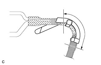
Using tape or equivalent, cover the area indicated in the illustration.
-
Insert the claw of a new wire harness protector into the hole in the side member and turn the claw until it touches the side member.
Note
Do not twist the electric oil pump harness more than 360° when installing it.
-
-
INSTALL WIRE HARNESS CLAMP
-
Align the matchmarks and install 9 new clamps to the wire.
Note
Be sure to install the wire harness clamps in the locations of the matchmarks placed during removal.
-
-
INSTALL HYBRID VEHICLE TRANSMISSION ASSEMBLY
-
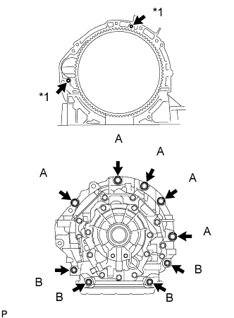
Text in Illustration *1 Knock Pin Make sure that the knock pins are installed on the engine.
-
Install the hybrid vehicle transmission assembly to the engine with the 9 bolts shown in the illustration.
- Torque:
- for Bolt A
- 71 N*m { 724 kgf*cm, 52 ft.*lbf }
- for Bolt B
- 37 N*m { 377 kgf*cm, 27 ft.*lbf }
Note
-
Do not use excessive force to pry on the hybrid vehicle transmission assembly.
-
Do not apply grease either to the splines or input shaft.
Tech Tips
Bolt A: 50 mm (1.97 in.)
Bolt B: 43 mm (1.69 in.)
-
-
INSTALL FLYWHEEL HOUSING SIDE COVER
-
Install the flywheel housing side cover.
-
-
INSTALL STARTER HOLE INSULATOR
-
Install the starter hole insulator with the 2 bolts.
- Torque:
- 58 N*m { 591 kgf*cm, 43 ft.*lbf }
-
-
INSTALL TRANSMISSION BREATHER HOSE SUB-ASSEMBLY
-
Install the transmission breather hose sub-assembly with the clamp.
-
Connect the transmission breather hose sub-assembly to the oil with motor pump assembly, and slide the clamp to secure it.
-
Install the transmission breather hose with the 2 bolts.
- Torque:
- 7.0 N*m { 71 kgf*cm, 62 in.*lbf }
-
Install a new O-ring.
-
Coat the O-ring with ATF.
-
Install the transmission breather plug.
-
-
INSTALL OIL COOLER UNION SUB-ASSEMBLY
-
Temporarily install the oil cooler union sub-assembly and 4 new gaskets with the 2 union bolts and bolt.
-
Tighten the 2 union bolts and bolt.
- Torque:
- for Bolt A (Union Bolt)
- 28 N*m { 280 kgf*cm, 20 ft.*lbf }
- for Bolt B
- 12 N*m { 122 kgf*cm, 9 ft.*lbf }
-
-
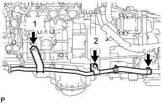
INSTALL WATER PIPE AND HOSE SUB-ASSEMBLY
-
for RH Side:
-
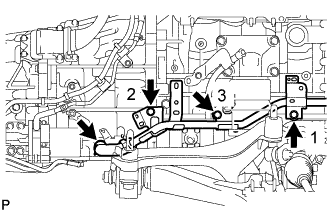
Install the 3 bolts to the water pipe and hose sub-assembly in the order shown in the illustration.
- Torque:
- 22 N*m { 224 kgf*cm, 16 ft.*lbf }
-
Connect the water pipe and hose sub-assembly to the hybrid vehicle transmission assembly, and slide the clip to secure it.
-
-
for LH Side:
-
Install the 2 bolts to the water pipe and hose sub-assembly in the order shown in the illustration.
- Torque:
- 22 N*m { 224 kgf*cm, 16 ft.*lbf }
-
Connect the water pipe and hose sub-assembly to the hybrid vehicle transmission assembly, and slide the clip to secure it.
-
-
-
INSTALL OIL COOLER HOSE TUBE SUB-ASSEMBLY
-
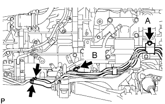
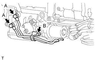
Install the oil cooler hose tube sub-assembly with the 2 bolts.
- Torque:
- for Bolt A
- 12 N*m { 122 kgf*cm, 9 ft.*lbf }
- for Bolt B
- 8.0 N*m { 82 kgf*cm, 71 in.*lbf }
-
Connect the oil cooler hose tube sub-assembly to the oil cooler union sub-assembly, and slide the 2 clips to secure it.
-
-
INSTALL TRANSMISSION CONTROL SHAFT LEVER
-
Install the transmission control shaft lever with the spring washer and nut.
- Torque:
- 16 N*m { 160 kgf*cm, 12 ft.*lbf }
-
-
INSTALL REAR NO. 1 ENGINE MOUNTING INSULATOR
Tech Tips
Only perform this procedure when replacement of the engine mounting insulator is necessary.
-
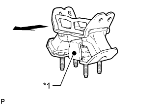
Text in Illustration *1 Paint Mark 
Rear of Vehicle Install the rear No. 1 engine mounting insulator to the hybrid vehicle transmission assembly with the 4 bolts.
- Torque:
- 52 N*m { 530 kgf*cm, 38 ft.*lbf }
Tech Tips
Make sure that the paint mark faces toward the rear of the vehicle.
-
-
INSTALL REAR ENGINE MOUNTING MEMBER
-
Install the engine rear mounting member to the hybrid vehicle transmission assembly with the 4 nuts.
- Torque:
- 13 N*m { 133 kgf*cm, 10 ft.*lbf }
-
-
INSTALL MOTOR CABLE
Note
When installing the motor cable, minimize bending of the transmission end of the cable.
-
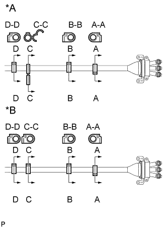
Text in Illustration *A for LHD: *B for RHD: Align the matchmarks and install the 4 clamps to the motor cable.
Note
Be sure to install the wire harness clamps in the locations of the matchmarks placed during removal.
-
Install the 3 O-rings to the terminal cables.
Note
-
Check that the O-rings are not damaged before installing.
-
Install the O-rings making sure that they do not come out of the groove.
-
Do not get oil on the O-rings.
-
Check that the O-rings are not twisted.
-
-
Using a 5 mm hexagon wrench, tighten the 3 bolts.
- Torque:
- 8.0 N*m { 82 kgf*cm, 71 in.*lbf }
Note
-
When installing the motor cable, minimize bending of the transmission end of the cable.
-
Protect the terminal cables and the installation area from water and foreign objects.
-
Make sure that the O-rings do not get caught between any parts.
-
Make sure that the tightening torque is between of 6.4 to 9.6 N*m (66 to 97 kgf*cm, 57 to 84 in.*lbf).
Tech Tips
To avoid putting too much pressure on the motor cable and bending its end, hold the end of the motor cable in one hand and use the other hand to line the motor cable up and install it against the side of the engine.
-
Using an insulated tool, install the 2 bolts.
- Torque:
- 8.0 N*m { 82 kgf*cm, 71 in.*lbf }
Note
Make sure that the tightening torque is between of 6.4 to 9.6 N*m (66 to 97 kgf*cm, 57 to 84 in.*lbf).
-
Install 3 new terminal caps to the hybrid vehicle transmission.
Note
-
Make sure that the O-rings do not get caught between any parts.
-
Make sure that the terminals caps are installed securely.
-
-
Using an insulated tool, install the connector cover with the 2 bolts.
- Torque:
- 8.0 N*m { 82 kgf*cm, 71 in.*lbf }
Note
Make sure that the tightening torque is between of 6.4 to 9.6 N*m (66 to 97 kgf*cm, 57 to 84 in.*lbf).
-
-
INSTALL GENERATOR CABLE
Note
When installing the generator cable, minimize bending of the transmission end of the cable.
-
for LHD:
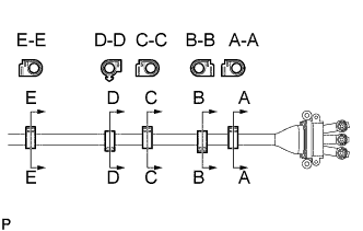
Align the matchmarks and install the 5 clamps to the generator cable.
Note
Be sure to install the wire harness clamps in the locations of the matchmarks placed during removal.
-
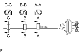
for RHD:
Align the matchmarks and install the 3 clamps to the generator cable.
Note
Be sure to install the wire harness clamps in the locations of the matchmarks placed during removal.
-
Install 3 new O-rings to the terminal cables.
Note
-
Check that the O-rings are not damaged before installing.
-
Install the O-rings making sure that they do not come out of the groove.
-
Do not get oil on the O-rings.
-
Check that the O-rings are not twisted.
-
-
Using a 5 mm hexagon wrench, tighten the 3 bolts.
- Torque:
- 8.0 N*m { 82 kgf*cm, 71 in.*lbf }
Note
-
When installing the motor cable, minimize bending of the transmission end of the cable.
-
Protect the terminal cables and the installation area from water and foreign objects.
-
Make sure that the O-rings do not get caught between any parts.
-
Make sure that the tightening torque is between of 6.4 to 9.6 N*m (66 to 97 kgf*cm, 57 to 84 in.*lbf).
Tech Tips
To avoid putting too much pressure on the generator cable and bending its end, hold the end of the generator cable in one hand and use the other hand to line the generator cable up and install it against the side of the engine.
-
Install the 2 bolts.
- Torque:
- 8.0 N*m { 82 kgf*cm, 71 in.*lbf }
Note
Make sure that the tightening torque is between of 6.4 to 9.6 N*m (66 to 97 kgf*cm, 57 to 84 in.*lbf).
-
Install 3 new terminal caps to the hybrid vehicle transmission.
Note
-
Be careful that the O-ring does not get caught between the parts.
-
Make sure that the terminal caps are installed securely.
-
-
Install the connector cover with the 2 bolts.
- Torque:
- 8.0 N*m { 82 kgf*cm, 71 in.*lbf }
Note
Make sure that the tightening torque is between of 6.4 to 9.6 N*m (66 to 97 kgf*cm, 57 to 84 in.*lbf).
-
for RHD:
Connect the 2 generator cable clamps.
-
for LHD:
Connect the 4 generator cable clamps.
-
-
CONNECT WIRE HARNESS
Note
When installing the motor cable and generator cable, minimize bending of the transmission end of the cable.
-
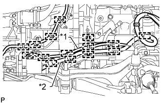
Text in Illustration *1 Signal Line *2 Power Line Connect the 15 wire harness clamps to the hybrid vehicle transmission assembly.
Note
Do not cross or entangle the signal line and power line.
-
Install the wire harness to the hybrid vehicle transmission assembly with the 3 bolts and clamp.
-
for RHD:
Connect the 5 cable clamps.
-
for LHD:
Connect the 6 cable clamps.
-
Install the ground cable with the bolt.
- Torque:
- 10 N*m { 102 kgf*cm, 7 ft.*lbf }
-
-
CONNECT CONNECTOR
-
Connect the shift lever position sensor connector, transmission wire connector, transmission speed sensor connector, engine oil level sensor connector, O/P THERM connector, oil pressure sensor connector, generator revolution connector and motor revolution connector.
Note
Make sure that the wire harness for the oil level sensor is positioned in front of the wire harness of the electrical oil pump.
-
-
INSTALL ENGINE WITH TRANSMISSION
-
PERFORM RESET MEMORY
-
If the hybrid vehicle transmission assembly is replaced, initialize the learning value of the transmission Click here.
-
-
B1 AIR BLEEDING
-
Inspect the Control the Shift Position Click here.
-
Connect the GTS to the DLC3.
-
Turn the power switch on (READY) and turn the GTS on.
Note
-
Make sure that the shift lever is in P and the air conditioning is off before turning the power switch on (READY) and turning the GTS on.
-
Make sure that no DTCs are output.
-
Make sure that the transmission fluid temperature is between 0°C to 79°C (32°F to 175°F).
-
-
Enter the following menus: Powertrain / Hybrid Control / Utility / B1 Air Bleeding.
Note
-
Do not move the shift lever from P.
-
Do not turn on the air conditioning while bleeding the air from the B1 chamber.
Tech Tips
It takes about 5 minutes to bleed the air from the B1 chamber.
-
-
Inspect the Control the Shift Position Click here.
-