DRIVING SUPPORT ECU INSTALLATION

Tech Tips
-
Use the same procedures for LHD and RHD vehicles.
-
The procedures listed below are for LHD vehicles.
-
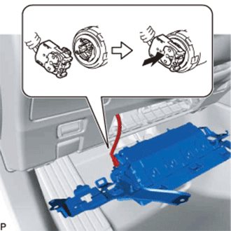
INSTALL DRIVING SUPPORT ECU
Note
-
Do not use an ECU which has been dropped or subjected to any strong shocks.
-
When a new ECU is installed, perform initialization Click here.
-
Install the driving support ECU with the 2 nuts.
- Torque:
- 7.5 N*m { 76 kgf*cm, 66 in.*lbf }
-
-
INSTALL COWL SIDE JUNCTION BLOCK LH
-
Install the cowl side junction block LH with the bolt and nut.
- Torque:
- 8.0 N*m { 82 kgf*cm, 71 in.*lbf }
-
-
INSTALL LOWER NO. 1 INSTRUMENT PANEL AIRBAG ASSEMBLY
-
Check that the power switch is off.
-
Check that the cable is disconnected from the negative (-) auxiliary battery terminal.
CAUTION:
Wait at least 90 seconds after disconnecting the cable from the negative (-) auxiliary battery terminal to disable the SRS system.
-
Connect the airbag connector to the lower No. 1 instrument panel airbag assembly.
Note
When connecting any airbag connector, take care not to damage the airbag wire harness.
-
Push in the lock to install the airbag connector.
-
Attach the 3 claws to connect the hood lock control lever sub-assembly to the lower No. 1 instrument panel airbag assembly.
-
Temporarily install the lower No. 1 instrument panel airbag assembly with the hook and pin.
-
Install the lower No. 1 instrument panel airbag assembly with the 4 bolts.
- Torque:
- 10 N*m { 102 kgf*cm, 7 ft.*lbf }
Note
Confirm that the lower No. 1 instrument panel airbag assembly is installed securely without any excessive gaps and is not protruding outward.
-
-
INSTALL NO. 1 INSTRUMENT PANEL SAFETY PAD SUB-ASSEMBLY
-
Connect the connectors.
-
Attach the 9 clips and guide to install the No. 1 instrument panel safety pad sub-assembly.
-
-
INSTALL INSTRUMENT PANEL FINISH PANEL END LH
-
Attach the 5 clips and 2 guides to install the instrument panel finish panel end LH.
-
-
INSTALL CENTER INSTRUMENT CLUSTER FINISH PANEL
-
Connect the connector.
-
Attach the 9 clips and guide to install the center instrument cluster finish panel.
-
-
INSTALL NO. 1 INSTRUMENT PANEL UNDER COVER SUB-ASSEMBLY
-
Connect the connectors and attach the clamp.
-
Attach the 2 claws to install the No. 1 instrument panel under cover sub-assembly.
-
Install the 3 screws <A>.
-
-
INSTALL NO. 1 INSTRUMENT PANEL GARNISH SUB-ASSEMBLY
-
Attach the 4 clips to install the No. 1 instrument panel garnish sub-assembly.
-
-
INSTALL INSTRUMENT SIDE PANEL LH
-
Attach the 7 clips to install the instrument side panel LH.
-
-
CONNECT CABLE TO AUXILIARY BATTERY NEGATIVE TERMINAL
Note
When disconnecting the cable, some systems need to be initialized after the cable is reconnected Click here.
-
INSTALL LUGGAGE COMPARTMENT TRIM COVER LH
-
Install the luggage compartment trim cover LH.
-
-
INSTALL LUGGAGE COMPARTMENT FLOOR MAT
-
Install the luggage compartment floor mat.
-
-
CHECK SRS WARNING LIGHT