LANE-KEEPING ASSIST SYSTEM, Diagnostic DTC:C1A05

| DTC Code | DTC Name |
|---|---|
| C1A05 | Stop Light Switch Circuit |
DESCRIPTION
When the brake pedal is depressed, the stop light switch assembly sends a brake pedal operation signal to the driving support ECU. After reception of this signal, the driving support ECU cancels the radar cruise control system. When the driving support ECU detects a problem in the stop light switch circuit, DTC C1A05 is stored.
| DTC Code | DTC Detection Condition | Trouble Area |
|---|---|---|
| C1A05 |
|
|
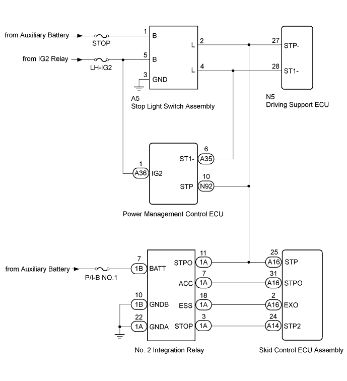
WIRING DIAGRAM
INSPECTION PROCEDURE
Note
-
Inspect the fuses for circuits related to this system before performing the following inspection procedure.
-
When replacing the driving support ECU, always replace it with a new one and be sure to perform initialization Click here. If an ECU which was installed to another vehicle is used, the information stored in the ECU will not match the information from the vehicle, and as a result, a DTC may be stored.
PROCEDURE
-
READ VALUE USING GTS (Stop Light SW)
-
Check the Data List for proper functioning of the stop light switch Click here.
Radar Cruise Tester Display Measurement Item/Range Normal Condition Diagnostic Note Stop Light SW 1 (M CPU) Stop light switch (Main-CPU) signal / ON or OFF ON: Depress brake pedal
OFF: Release brake pedal
- Stop Light SW 2 (M CPU) Stop light switch (Main-CPU) signal / ON or OFF ON: Depress brake pedal
OFF: Release brake pedal
- Stop Light SW 1 (S CPU) Stop light switch (Sub-CPU) signal / ON or OFF ON: Depress brake pedal
OFF: Release brake pedal
- OK Display changes according to brake pedal operation described in above table.
NG 
CHECK HARNESS AND CONNECTOR (STOP LIGHT SWITCH ASSEMBLY - BATTERY AND BODY GROUND) Click here
OK 
-
-
CHECK HARNESS AND CONNECTOR (NO. 2 INTEGRATION RELAY - BATTERY AND BODY GROUND)
-
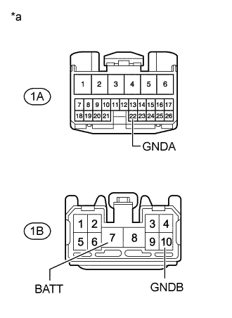
Text in Illustration *a Front view of wire harness connector
(to No. 2 Integration Relay)
Disconnect the No. 2 integration relay connectors.
-
Measure the voltage according to the value(s) in the table below.
Standard Voltage Tester Connection Condition Specified Condition 1B-7 (BATT) - Body ground Always 11 to 14 V -
Measure the resistance according to the value(s) in the table below.
Standard Resistance Tester Connection Condition Specified Condition 1A-22 (GNDA) - Body ground Always Below 1 Ω 1B-10 (GNDB) - Body ground Always Below 1 Ω
NG 
REPAIR OR REPLACE HARNESS OR CONNECTOR
OK
-
-
CHECK HARNESS AND CONNECTOR (NO. 2 INTEGRATION RELAY - STOP LIGHT SWITCH ASSEMBLY)
-
Disconnect the 1A No. 2 integration relay connector.
-
Disconnect the A5 stop light switch assembly connector.
-
Measure the resistance according to the value(s) in the table below.
Standard Resistance Tester Connection Switch Condition Specified Condition 1A-11 (STPO) - A5-2 (L) Always Below 1 Ω 1A-11 (STPO) - Body ground Always 10 kΩ or higher
NG
REPAIR OR REPLACE HARNESS OR CONNECTOR
OK
-
-
CHECK HARNESS AND CONNECTOR (STOP LIGHT SWITCH ASSEMBLY - SKID CONTROL ECU ASSEMBLY)
-
Disconnect the A5 stop light switch assembly connector.
-
Disconnect the A16 skid control ECU assembly connector.
-
Measure the resistance according to the value(s) in the table below.
Standard Resistance Tester Connection Switch Condition Specified Condition A5-2 (L) - A16-25 (STP) Always Below 1 Ω A5-2 (L) - Body ground Always 10 kΩ or higher
NG
REPAIR OR REPLACE HARNESS OR CONNECTOR
OK
-
-
CHECK HARNESS AND CONNECTOR (NO. 2 INTEGRATION RELAY - SKID CONTROL ECU ASSEMBLY)
-
Disconnect the 1A No. 2 integration relay connector.
-
Disconnect the A14 and A16 skid control ECU assembly connectors.
-
Measure the resistance according to the value(s) in the table below.
Standard Resistance Tester Connection Switch Condition Specified Condition 1A-11 (STPO) - A16-25 (STP) Always Below 1 Ω 1A-7 (ACC) - A16-31 (STPO) Always Below 1 Ω 1A-3 (STOP) - A14-24 (STP2) Always Below 1 Ω 1A-18 (ESS) - A16-2 (EXO) Always Below 1 Ω 1A-11 (STPO) - Body ground Always 10 kΩ or higher 1A-7 (ACC) - Body ground Always 10 kΩ or higher 1A-3 (STOP) - Body ground Always 10 kΩ or higher 1A-18 (ESS) - Body ground Always 10 kΩ or higher
NG
REPAIR OR REPLACE HARNESS OR CONNECTOR
OK
-
-
INSPECT NO. 2 INTEGRATION RELAY
-
Remove the No. 2 integration relay Click here.
-
Inspect the No. 2 integration relay Click here.
NG
REPLACE NO. 2 INTEGRATION RELAY Click here
OK
-
-
REPLACE SKID CONTROL ECU ASSEMBLY
-
Temporarily replace the skid control ECU assembly with a new or normally functioning one Click here.
NEXT
-
-
CHECK FOR DTC
-
Clear the DTCs Click here.
-
Make sure the following conditions are met:
Tech Tips
If the detection conditions are not met, the system cannot detect malfunctions.
-
Radar cruise control system:
The vehicle is being driven at a speed of approximately 50 km/h (31 mph) or more and the ACC main switch is on.
-
Lane keeping assist system:
The vehicle is being driven at a speed of approximately 50 km/h (31 mph) or more and the lane-keeping assist main switch is on.
-
The brake pedal is depressed for 1 second or more.
-
-
Check for DTCs Click here.
OK DTC C1A05 is not output.
NG
REPLACE POWER MANAGEMENT CONTROL ECU Click here
OK 
END (SKID CONTROL ECU ASSEMBLY IS DEFECTIVE)
-
-
REPLACE POWER MANAGEMENT CONTROL ECU
-
Temporarily replace the power management control ECU with a new one Click here.
NEXT
-
-
CHECK FOR DTC
-
Check for DTCs Click here.
-
Make sure the following conditions are met:
Tech Tips
If the detection conditions are not met, the system cannot detect malfunctions.
-
Radar cruise control system:
The vehicle is being driven at a speed of approximately 50 km/h (31 mph) or more and the ACC main switch is on.
-
Lane keeping assist system:
The vehicle is being driven at a speed of approximately 50 km/h (31 mph) or more and the lane-keeping assist main switch is on.
-
The brake pedal is depressed for 1 second or more.
-
-
Check for DTCs Click here.
OK DTC C1A05 is not output.
NG
REPLACE DRIVING SUPPORT ECU Click here
OK
END (POWER MANAGEMENT CONTROL ECU IS DEFECTIVE)
-
-
CHECK HARNESS AND CONNECTOR (STOP LIGHT SWITCH ASSEMBLY - BATTERY AND BODY GROUND)
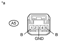
Text in Illustration *a Front view of wire harness connector
(to Stop Light Switch Assembly)
-
Disconnect the stop light switch assembly connector.
-
Measure the voltage according to the value(s) in the table below.
Standard Voltage Tester Connection Condition Specified Condition 5A-1 (B) - Body ground Always 11 to 14 V 5A-5 (B) - Body ground Power switch on (IG) 11 to 14 V -
Measure the resistance according to the value(s) in the table below.
Standard Resistance Tester Connection Switch Condition Specified Condition A5-3 (GND) - Body ground Always Below 1 Ω
NG
REPAIR OR REPLACE HARNESS OR CONNECTOR
OK
-
-
CHECK STOP LIGHT SWITCH ASSEMBLY
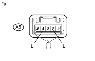
Text in Illustration *a Component with harness connected
(Stop Light Switch Assembly)
-
Reconnect the stop light switch assembly connector.
-
Measure the voltage according to the value(s) in the table below.
Standard Voltage Tester Connection Condition Specified Condition 5A-2 (L) - Body ground Brake pedal depressed 11 to 14 V 5A-4 (L) - Body ground 5A-2 (L) - Body ground Brake pedal released Below 1 V 5A-4 (L) - Body ground
NG
REPLACE STOP LIGHT SWITCH ASSEMBLY Click here
OK
-
-
CHECK HARNESS AND CONNECTOR (STOP LIGHT SWITCH ASSEMBLY - DRIVING SUPPORT ECU)
-
Disconnect the A5 stop light switch assembly connector.
-
Disconnect the N5 driving support ECU connector.
-
Measure the resistance according to the value(s) in the table below.
Standard Resistance Tester Connection Switch Condition Specified Condition A5-2 (L) - N5-27 (STP-) Always Below 1 Ω A5-4 (L) - N5-28 (ST1-) Always Below 1 Ω A5-2 (L) - Body ground Always 10 kΩ or higher A5-4 (L) - Body ground Always 10 kΩ or higher
NG
REPAIR OR REPLACE HARNESS OR CONNECTOR
OK
-
-
CHECK HARNESS AND CONNECTOR (POWER MANAGEMENT CONTROL ECU - DRIVING SUPPORT ECU)
-
Disconnect the A35 and N92 power management control ECU connectors.
-
Disconnect the N5 driving support ECU connector.
-
Measure the resistance according to the value(s) in the table below.
Standard Resistance Tester Connection Switch Condition Specified Condition N92-10 (STP) - N5-27 (STP-) Always Below 1 Ω A35-6 (ST1-) - N5-28 (ST1-) Always Below 1 Ω A35-6 (ST1-) - Body ground Always 10 kΩ or higher N92-10 (STP) - Body ground Always 10 kΩ or higher
NG
REPAIR OR REPLACE HARNESS OR CONNECTOR
OK
REPLACE DRIVING SUPPORT ECU Click here
-