LANE RECOGNITION CAMERA SENSOR INSTALLATION

Tech Tips
A bolt without a torque specification is shown in the standard bolt chart Click here.
-
INSTALL LANE RECOGNITION CAMERA SENSOR ASSEMBLY
-
Attach the guide and clip to temporarily install the lane recognition camera sensor assembly.
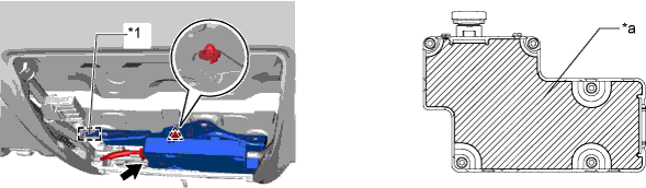
Text in Illustration *1 Guide - - *a Center part of the sensor - - Note
-
Do not install the recognition camera sensor assembly if it has been damaged or impacted in any way.
-
If the sensor is not installed securely, beam axis learning may not complete, preventing the system from operating normally. Make sure to install the sensor securely.
-
Do not touch the lens of the camera sensor during installation.
-
Pull the harness slightly to allow it to hang down.
-
When engaging the clip, push on the edge of the sensor, near the screws, or on the bracket.
-
To prevent deformation of the sensor, do not push on the center part of the sensor.
-
-
Temporarily install the lane recognition camera sensor assembly with the 3 bolts.
-
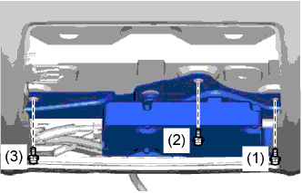
Tighten the 3 bolts in the order as shown in the illustration to install the lane recognition camera sensor assembly.
-
Connect the connector.
-
-
INSTALL MAP LIGHT ASSEMBLY
-
Connect the 2 connectors.
-
Attach the 4 clips and 2 guides to install the map light assembly.
-
-
INSTALL FRONT ROOF TOP GARNISH
-
w/ Night View System:
-
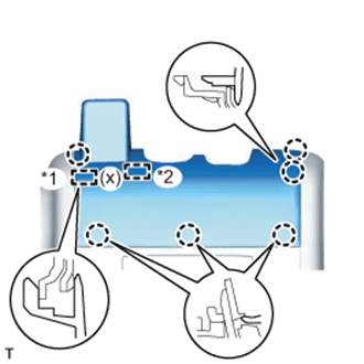
While being careful not to apply force to the camera, attach the 6 claws, guide and fastener to install the front roof top garnish.
Text in Illustration *1 Guide *2 Fastener Note
When removing and installing the front roof top garnish, do not apply force to the camera sensor located at (x).
-
-
w/o Night View System:
-
While being careful not to apply force to the camera (for vehicles with the lane keeping assist system), attach the 6 claws and guide to install the front roof top garnish.
Note
w/ Lane Keeping Assist System:
When removing and installing the front roof top garnish, do not apply force to the camera sensor located at (x).
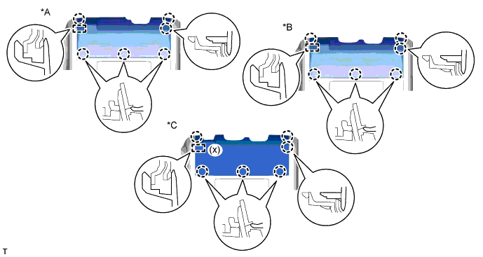
Text in Illustration *A for Standard *B w/ Rain Sensor *C w/ Lane Keeping Assist System - -
-
-
-
ADJUST LANE RECOGNITION CAMERA SENSOR ASSEMBLY
Note
-
Make sure that there are no black and white patterned objects in front of the vehicle.
-
Be sure to perform the measurement on a level surface that is free of obstacles and extends 1.5 m (4.92 ft.) or more in front of the vehicle.
-
Make sure that there is no wind when performing the measurement.
-
Check that there are no reflective materials in the surroundings or on the ground within a 1.5 m (4.92 ft.) x 3 m (9.84 ft.) area in front of the vehicle.
-
Perform the inspection in a bright area.
-
Prepare for beam axis learning.
-
Move the vehicle to a level surface.
-
Make sure the engine oil in the vehicle is at the specified level.
-
Make sure the engine coolant in the vehicle is at the specified level.
-
Make sure the fuel tank is full.
-
Make sure the spare tire is in the vehicle.
-
Make sure the standard tools are in the vehicle.
-
Make sure nobody is in the vehicle.
-
Make sure no extra loads are in the vehicle.
-
Adjust the tire pressures to the specified pressure Click here.
-
Clean the windshield.
-
If the lens of the lane recognition camera sensor is dirty, apply a small amount of lens cleaner to a clean and soft cloth, and clean the lens.
-
-
Perform the front wheel alignment adjustment.
-
Perform the front wheel alignment adjustment Click here.
Note
Perform this procedure as accurately as possible.
-
-
Perform the rear wheel alignment adjustment.
-
Perform the rear wheel alignment adjustment Click here.
Note
Perform this procedure as accurately as possible.
-
-
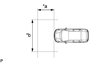
Create a target sheet.
-
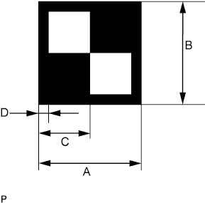
Text in Illustration *a 1.5 m (4.92 ft.) or more *b 3 m (9.84 ft.) or more Print or copy the illustration. Check that the dimensions are +/- 5 mm (0.197 in.) of the ones in the table below.
Dimension Area Specification A 160 mm (6.30 in.) B 160 mm (6.30 in.) C 80 mm (3.15 in.) D 16 mm (0.630 in.) Note
-
Make sure that the black areas of the target sheet are not glossy.
-
Make sure that the borders of the black and white areas on the target sheet are straight, and are not warped or blurry.
If the print or copy's dimensions are not as specified, adjust settings and reprint or recopy so that the print or copy's dimensions are as specified.

-
-
-
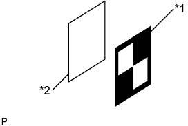
Text in Illustration *1 Target Sheet *2 Cardboard, etc. Attach the target sheet.
-
Place the prepared target sheet on a piece of cardboard of the same size, and position the black area on the top right as shown in the illustration. Then use double-sided tape to fix the target sheet in place.
Note
Do not attach reflective tape, such as transparent adhesive tape, etc. to the target face, as this may affect target recognition.
-
Hang a weight with a pointed tip from the center of the target sheet.
-
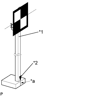
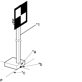
Text in Illustration *1 SST (Radar Adjusting Reflector) *2 Plumb Bob (Weight with Pointed Tip) *a Mark-off Line Attach the target sheet to SST (radar adjusting reflector) with double-sided tape so that the tip of the weight aligns with the mark-off line.
- SST
- 09870-60000 ( 09870-60010, 09870-60020 )
Note
-
Perform this procedure as accurately as possible.
-
Attach the target sheet so that the bottom edge is parallel with the ground.
-
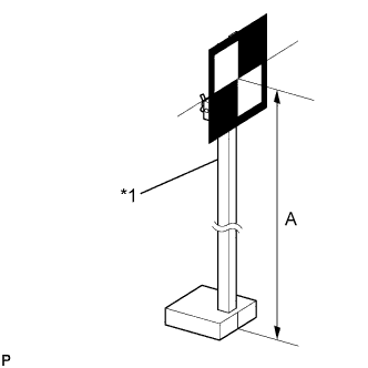
Text in Illustration *1 SST (Radar Adjusting Reflector) Move the reflector up and down to position the center of the target at the height shown in the illustration, and fix it in place.
Dimension A 850 mm (33.5 in.) - SST
- 09870-60000 ( 09870-60010, 09870-60020 )
Note
Perform this procedure as accurately as possible.
-
-
Measure the target placement point.
Note
-
Do not place black and white patterned objects near the target.
-
Face the vehicle toward a wall with no patterns, or make sure the background behind the target has no patterns.
-
Perform this procedure as accurately as possible.
-
Do not place reflective materials in the area behind the target.
-
Make sure the target is within 3 m (9.84 ft.) of the wall.
-
Make sure the target's shadow is not on the wall, as the camera may have a recognition error.
-
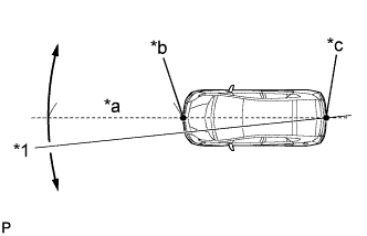
Text in Illustration *1 Line *a Approx. 2 m (6.56 ft.) *b Point A *c Point B From the center of the front and back bumpers (center of the emblems), hang a weight with a pointed tip, and mark the front bumper center on the ground as point A and the rear bumper center on the ground as point B.
-
Draw a line that connects points A and B, and extend the line approximately 2 m (6.56 ft.) beyond the front of the vehicle.
Tech Tips
Secure the end of a string to point B. Then hold the other end of the string approximately 2 m (6.56 ft.) in front of the vehicle, and move it to the left or right to align the string with point A to make a straight line.
-
Mark point C 1008 mm (40.0 in.) from the front bumper center point A (this is placement point 1).
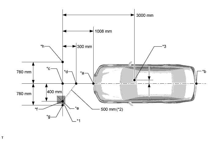
Text in Illustration *1 Marking Tape *2 Measuring Tape *3 Lane Recognition Camera Sensor Position - - *a Point A *b Point B *c Point C (Placement Point 1) *d Point D *e Line E *f Point F *g Point G (Placement Point 2) *h Point H (Placement Point 3) Exchange Table mm in. 3000 118 1008 40.0 780 30.7 300 11.8 400 15.7 500 19.7 -
From point C, move 300 mm (11.8 in.) toward the front bumper center point A and mark point D.
-
From point C, place marking tape at a point 400 mm (15.7 in.) perpendicular to the line that connects points A and B.
Note
Place the tape so that there is plenty of surface area along the perpendicular line.
-
Using a measuring tape of 5 m (16.4 ft.) or more, with point D as the center point, draw the part of a 500 mm (19.7 in.) circle that overlaps the marking tape (line E).
-
Mark point F where the following intersect: 1) from point C, the point that is 400 mm (15.7 in.) perpendicular from the line that connects point A and B; and 2) line E.
Tech Tips
The purpose of the above step is to ensure that point F is placed exactly perpendicular to the line that passes through points A and B.
-
Set the measuring tape from point C to F. Then mark point G 780 mm (30.7 in.) from point C (on a line extending from point C through F) (this is placement point 2).
-
Set the measuring tape from point F to C. Then mark point H 780 mm (30.7 in.) beyond point C (this is placement point 3).
-
Set a string between points G and H, and draw a line on the ground (target placement line).
-
-
Measure the lane recognition camera sensor height.
Note
-
Do not place black and white patterned objects near the target.
-
Face the vehicle toward a wall with no patterns, or make sure the background behind the target has no patterns.
-
Perform this procedure as accurately as possible.
-
Do not place reflective materials in the area behind the target.
-
Make sure the target is within 3 m (9.84 ft.) of the wall.
-
Make sure the target's shadow is not on the wall, as this may cause the camera to have a recognition error.
-
Measure the distance (X mm or in.) from the ground to point H for the front left wheel arch.
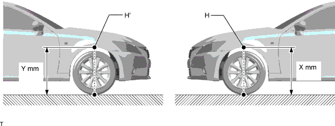
-
Measure the distance (Y mm or in.) from the ground to point H' for the front right wheel arch.
-
The average of the 2 distances (X mm or in, Y mm or in.) plus 610 mm (24.0 in.) is the height of the lane recognition camera sensor.
-
-
Memorize camera/target position.
Note
-
Close all doors.
-
Perform the procedure with no one in the vehicle.
-
During the procedure, do not lean on the vehicle.
-
Turn on the clearance lights.
-
Do not turn on the headlights.
-
When using the GTS:
-
Connect the GTS to the DLC3.
-
Turn the power switch on (IG).*1
-
Turn the GTS on.
-
Select "Chassis" from the display screen.
-
Select "Lane Keeping Assist" from the display screen.
-
Select "Utility" from the display screen.
-
Select "Camera/Target Position Memory".
Tech Tips
A buzzer will sound for 1 second.
-
Follow the GTS display, and continue with the adjustment.
-
-
Input the measured height of the lane recognition camera sensor and input "76 mm (2.99 in.)" for the horizontal position of the camera into the input screen. Then press the "Enter" button on the display screen.
-
Input "3000 mm (118 in.)" for the distance from the camera to the target and "850 mm (33.5 in.)" for the height of the target into the input screen. Then press the "Enter" button on the display screen.
-
Press the "Exit" button to finish the camera/target position memory mode.
Note
If "Error Camera/target position memory" is displayed on the screen, press the "Try Again" button, and repeat the procedure from *1 again.
-
-
Perform beam axis learning.
-
Select "Chassis" from the display screen.
-
Select "Lane Keeping Assist" from the display screen.*1
-
Select "Utility" from the display screen.
-
Select "Camera Axis Adjust" from the display screen.
-
Follow the GTS display, and continue with the adjustment.
-
Text in Illustration *1 SST (Radar Adjusting Reflector) *a Mark-off Line *b Point C *c Target Placement Line Align the target with the target placement line, and align the mark-off line with placement point 1 (point C).
-
Check that the screen displays beam axis learning for target 1, and then press the "Enter" button on the display screen.
-
Text in Illustration *1 SST (Radar Adjusting Reflector) *a Mark-off Line *b Point G *c Target Placement Line Align the target with the target placement line, and align the mark-off line with placement point 2 (point G).
-
Check that the screen displays beam axis learning for target 2, and then press the "Enter" button on the display screen.
Note
Within 3 minutes after the screen displays the beam axis learning for target 2, move the target and press the "Enter" button on the display screen.
-
Text in Illustration *1 SST (Radar Adjusting Reflector) *a Mark-off Line *b Point H *c Target Placement Line Align the target with the target placement line, and align the mark-off line with placement point 3 (point H).
-
Check that the screen displays beam axis learning for target 3, and then press the "Enter" button on the display screen.
Note
Within 3 minutes after the screen displays the beam axis learning for target 3, move the target and press the "Enter" button on the display screen.
-
Press the "Exit" button to finish the beam axis learning mode.
Note
If "Error camera axis adjust" is displayed on the screen, press the "Exit" button. Then after checking the conditions below, turn the power switch on (IG) and off, and repeat the procedure from *1 again.
-
Height of the target
-
Distance from lane recognition camera sensor to target
-
Orientation of target (black area positioned on top right)
-
If the surrounding area is bright enough
-
If black and white patterned objects are placed near the target
-
-
-
-
ROAD TEST
Tech Tips
The system may not operate normally under the following conditions:
-
The lane markers are difficult to see because they are blurry, backlit, or because of bad weather or puddles.
-
There are ruts in the snow on a road, or strips of snow on the road.
-
There are streaks of light from streetlights or headlights of oncoming vehicles that are reflected by a wet road.
-
There are patches of sunlight and shade on the road.
-
There is a stretch of guardrail or curb.
-
There are traces of old lane markers on the road.
-
The width of the lane markers is less than 150 mm (5.91 in.).
-
The vehicle-to-vehicle distance is extremely short.
-
The temperature of the lane recognition camera sensor body is -20°C (-4°F) or less or 60°C (140°F) or more.
-
Road Test
CAUTION:
Drive very carefully.
Note
Make sure to perform a road test and check for proper operation of the system after performing beam axis learning.
-
Turn the lane keeping assist main switch on, and turn the cruise control off using the cruise control main switch (this actuates the lane departure warning function).
Note
Perform the road test with the lane departure warning function activated.
Tech Tips
The lane keeping assist function is activated when the lane keeping assist main switch is turned on while the cruise control system is operating and the vehicle is in vehicle-to-vehicle distance control mode.
-
Drive the vehicle near the center marker at a speed of 60 km/h (37 mph) or more for 3 seconds or longer on a safe straight road with white or yellow center and side lane markers.
Note
-
Select an appropriate road or freeway where the vehicle can be safely driven at a speed of 60 km/h (37 mph) or more. The road that is selected should not be in use by pedestrians or bicycles.
-
Perform the road test on a flat straight road.
-
Exercise caution when steering the vehicle.
-
Avoid abrupt steering inputs.
-
Obey the speed limit.
Tech Tips
-
The lane recognition camera sensor can recognize dashed lane markers (the distance between markers should be 12 m (39.372 ft.) or less).
-
Lane departure warning mode operates when the vehicle speed is between 48 and 200 km/h (30 and 125 mph).
-
-

Check that the recognition indicator on the combination meter display comes on.
Tech Tips
If the indicator does not come on, check the following:
-
Installation condition of the lane recognition camera sensor
-
Wheel alignment
-
Location of the target
-
-
-