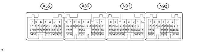
DYNAMIC RADAR CRUISE CONTROL SYSTEM TERMINALS OF ECU

-
CHECK POWER MANAGEMENT CONTROL ECU
-
Disconnect the A35, A36 and N92 power management control ECU connectors.
-
Measure the voltage according to the value(s) in the table below.
Terminal No. (Symbol) Wiring Color Terminal Description Condition Specified Condition A35-1 (+B2) - N91-6 (E1) W - W-B Power source Power switch on (IG) 11 to 14 V A35-6 (ST1-) - N91-6 (E1) GR - W-B Brake cancel signal Power switch on (IG), brake pedal depressed 0 to 1.5 V Power switch on (IG), brake pedal released 11 to 14 V A36-1 (IG2) - N91-6 (E1) B - W-B Power source Power switch on (IG) 11 to 14 V N92-10 (STP) - N91-6 (E1) R - W-B Stop light switch signal Brake pedal depressed 11 to 14 V Brake pedal released 0 to 1.5 V N92-20 (SFTD) - N91-6 (E1) W - W-B Transmission control Power switch on (IG), shift lever in S 11 to 14 V Power switch on (IG), shift lever in (-) 0 to 1.5 V N92-21 (SFTU) - N91-6 (E1) Y - W-B Transmission control Power switch on (IG), shift lever in S 11 to 14 V Power switch on (IG), shift lever in (+) 0 to 1.5 V N92-22 (M) - N91-6 (E1) R - W-B Transmission control Power switch on (IG), shift lever in S 11 to 14 V Power switch on (IG), shift lever not in S 0 to 1.5 V If the result is not as specified, there may be a malfunction on the wire harness side.
-
-
CHECK DRIVING SUPPORT ECU

-
Disconnect the N5 driving support ECU connector.
Note
If a load of more than 10 kg (22 lb.) is placed on the connector, it may break. Do not place more load than is necessary on the connector.
-
Measure the voltage and resistance according to the value(s) in the table below.
Terminal No. (Symbol) Wiring Color Terminal Description Condition Specified Condition N5-2 (CA3H) - N5-25 (GND) G - BR*1
G - W-B*2
CAN communication system Power switch on (IG) Pulse generation
(See waveform 1)
N5-6 (SPSW) - N5-25 (GND) Y - BR*1
Y - W-B*2
Distance control switch signal Power switch on (IG),
distance control switch off
1 MΩ or higher N5-6 (SPSW) - N5-25 (GND) Y - BR*1
Y - W-B*2
Distance control switch signal Power switch on (IG),
distance control switch on
Below 2.5 Ω N5-10 (CCHG) - N5-25 (GND) LG - BR*1
LG - W-B*2
Cruise control switch signal Cruise control main switch on,
MODE switch off
9 to 14 V N5-10 (CCHG) - N5-25 (GND) LG - BR*1
LG - W-B*2
Cruise control switch signal Cruise control main switch on,
MODE switch on
Below 1 V N5-17 (CA2L) - N5-25 (GND) LG - BR*1
LG - W-B*2
CAN communication system Power switch on (IG) Pulse generation
(See waveform 2)
N5-18 (CA1N) - N5-25 (GND) W - BR*1
W - W-B*2
CAN communication system Power switch on (IG) Pulse generation
(See waveform 2)
N5-20 (CA3L) - N5-25 (GND) SB - BR*1
SB - W-B*2
CAN communication system Power switch on (IG) Pulse generation
(See waveform 2)
N5-23 (CCS) - N5-25 (GND) GR - BR*1
GR - W-B*2
Cruise control switch signal Cruise control main switch on Below 2.5 Ω N5-23 (CCS) - N5-25 (GND) GR - BR*1
GR - W-B*2
Cruise control switch signal Cruise control main switch off 1 MΩ or higher N5-23 (CCS) - N5-25 (GND) GR - BR*1
GR - W-B*2
Cruise control switch signal +RES switch is held on 235 to 245 Ω N5-23 (CCS) - N5-25 (GND) GR - BR*1
GR - W-B*2
Cruise control switch signal -SET switch is held on 617 to 643 Ω N5-23 (CCS) - N5-25 (GND) GR - BR*1
GR - W-B*2
Cruise control switch signal CANCEL switch is held on 1509 to 1571 Ω N5-27 (STP-) - N5-25 (GND) R - BR*1
R - W-B*2
Stop light switch signal input Depress brake pedal 9 to 14 V N5-27 (STP-) - N5-25 (GND) R - BR*1
R - W-B*2
Stop light switch signal input Release brake pedal Below 1 V N5-28 (ST1-) - N5-25 (GND) GR - BR*1
GR - W-B*2
Stop light switch signal input Power switch on (IG),
release brake pedal
9 to 14 V N5-28 (ST1-) - N5-25 (GND) GR - BR*1
GR - W-B*2
Stop light switch signal input Power switch on (IG),
depress brake pedal
Below 1 V N5-32 (WIP2) - N5-25 (GND) L - BR*1
L - W-B*2
Windshield wiper switch signal Power switch on (IG),
windshield wiper switch off
Below 1 V N5-32 (WIP2) - N5-25 (GND) L - BR*1
L - W-B*2
Windshield wiper switch signal Power switch on (IG),
windshield wiper switch Hi
9 to 14 V N5-30 (B) - N5-25 (GND) L - BR*1
L - W-B*2
Power supply Power switch on (IG) 11 to 14 V N5-30 (B) - N5-25 (GND) L - BR*1
L - W-B*2
Power supply Power switch off Below 1 V N5-39 (CA2H) - N5-25 (GND) V - BR*1
V - W-B*2
CAN communication system Power switch on (IG) Pulse generation
(See waveform 1)
N5-40 (CA1P) - N5-25 (GND) G - BR*1
G - W-B*2
CAN communication system Power switch on (IG) Pulse generation
(See waveform 1)
-
*1: for LHD
-
*2: for RHD
If the result is not as specified, there may be a malfunction on the wire harness side.
-
-
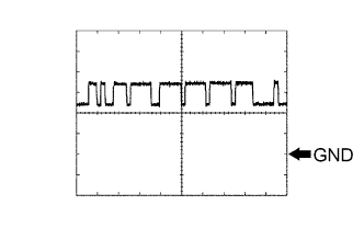
Using an oscilloscope, check waveform 1.
Measurement Condition Item Content Tester Connection
-
N5-2 (CA3H) - N5-25 (GND)
-
N5-39 (CA2H) - N5-25 (GND)
-
N5-40 (CA1P) - N5-25 (GND)
Tool Setting 1 V/DIV., 10 μs/DIV. Vehicle Condition Power switch on (IG) -
-
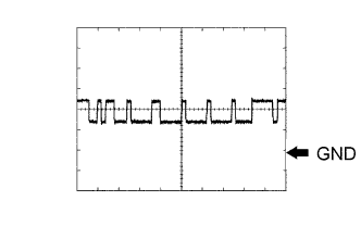
Using an oscilloscope, check waveform 2.
Measurement Condition Item Content Tester Connection
-
N5-17 (CA2L) - N5-25 (GND)
-
N5-18 (CA1N) - N5-25 (GND)
-
N5-20 (CA3L) - N5-25 (GND)
Tool Setting 1 V/DIV., 10 μs/DIV. Vehicle Condition Power switch on (IG) -
-