OIL PUMP INSTALLATION

-
INSTALL TIMING CHAIN COVER SUB-ASSEMBLY
-
Remove any old packing material remaining on the sealing surfaces before applying seal packing.
-
Clean and degrease the contact surfaces of the timing chain cover, cylinder head and cylinder block, and confirm that no oil, moisture or other foreign matter remains on the surfaces.
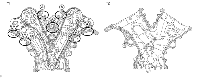
Text in Illustration *1 Cylinder Head and Cylinder Block *2 Timing Chain Cover 
Area to be cleaned and degreased - - Note
Be sure to clean and degrease the contact surfaces, especially the surfaces indicated by A in the illustration.
-
Install a new gasket.
-
Text in Illustration *a 3.0 mm (0.118 in.) or more Apply seal packing in a continuous line to the engine unit as shown in the illustration.
Seal packing Toyota Genuine Seal Packing Black, Three Bond 1207B or equivalent Seal diameter 3.0 mm (0.118 in.) or more Note
-
If the contact surfaces are wet, wipe them with an oil-free cloth before applying seal packing.
-
Install the chain cover within 3 minutes and tighten the bolts within 15 minutes after applying seal packing.
-
Do not add engine oil for at least 2 hours after installing the chain cover.
-
Do not start the engine for at least 2 hours after installing the chain cover.
-
-
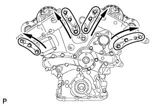
Apply seal packing in a line to the timing chain cover as shown in the following illustration.
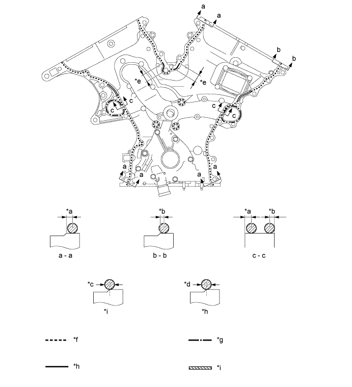
Text in Illustration *a 3.0 to 4.0 mm (0.118 to 0.157 in.) *b 2.0 to 3.0 mm (0.0787 to 0.118 in.) *c 6.0 mm (0.236 in.) or more *d 4.5 mm (0.177 in.) or more *e 20 mm (0.787 in.) *f Dashed line area
(Seal packing: Toyota Genuine Seal Packing Black, Three Bond 1207B or equivalent)
*g Alternate long and short dashed line area
(Seal packing: Toyota Genuine Seal Packing 1282B, Three Bond 1282B or equivalent)
*h Continuous line area
(Seal packing: Toyota Genuine Seal Packing Black, Three Bond 1207B or equivalent)
*i Diagonal line area
(Seal packing: Toyota Genuine Seal Packing Black, Three Bond 1207B or equivalent)
- - Seal Packing Application Chart Area Seal Packing Diameter Application Position from Inside Seal Line Diagonal Line Area 6.0 mm (0.236 in.) or more 3.0 to 4.0 mm (0.118 to 0.158 in.) Continuous Line Area 4.5 mm (0.177 in.) or more 3.0 to 4.0 mm (0.118 to 0.158 in.) Dashed Line Area 3.5 mm (0.138 in.) or more
-
a - a: 3.0 to 4.0 mm (0.118 to 0.158 in.)
-
b - b: 2.0 to 3.0 mm (0.0787 to 0.118 in.)
Alternate Long and Dashed Line Area 3.5 mm (0.138 in.) or more 2.0 to 3.0 mm (0.0787 to 0.118 in.) Seal packing Toyota Genuine Seal Packing Black, Three Bond 1207B or equivalent Toyota Genuine Seal Packing 1282B, Three Bond 1282B or equivalent Note
-
If the contact surfaces are wet, wipe them with an oil-free cloth before applying seal packing.
-
Install the chain cover within 3 minutes and tighten the bolts within 15 minutes after applying seal packing.
-
Do not add engine oil for at least 2 hours after installing.
-
Do not start the engine for at least 2 hours after installing.
-
-
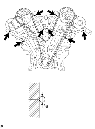
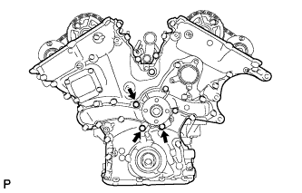
Text in Illustration *1 Drive Rotor Spline *2 Crankshaft Align the oil pump's drive rotor spline and the crankshaft as shown in the illustration. Install the chain cover to the crankshaft.
-
Type X:
-
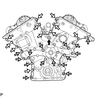
Temporarily tighten the timing chain cover with the 25 bolts and 2 nuts.
Text in Illustration 
Bolt A 
Bolt B 
Nut 
Bolt C Bolt Length Item Specified Condition Bolt A 50 mm (1.97 in.) Bolt B 25 mm (0.984 in.) Bolt C 55 mm (2.17 in.) Note
Make sure that there is no oil on the bolt threads.
-
-
Type Y:
-
Temporarily tighten the timing chain cover with the 25 bolts and 2 nuts.
Text in Illustration Bolt A Bolt B Nut Bolt C Bolt Length Item Specified Condition Bolt A 50 mm (1.97 in.) Bolt B 28 mm (1.102 in.) Bolt C 55 mm (2.17 in.) Note
Make sure that there is no oil on the bolt threads.
-
-
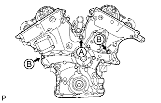
Fully tighten the 3 bolts shown in the illustration.
- Torque:
- for bolt A
- 43 N*m { 438 kgf*cm, 32 ft.*lbf }
- for bolt B
- 21 N*m { 214 kgf*cm, 15 ft.*lbf }
-
Fully tighten the 3 bolts shown in the illustration.
- Torque:
- 21 N*m { 214 kgf*cm, 15 ft.*lbf }
-
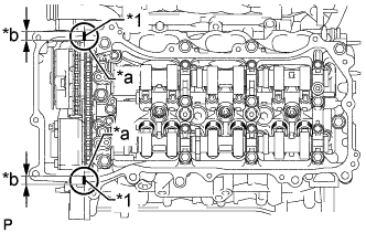
Text in Illustration *1 Nut Fully tighten the 7 bolts and 2 nuts shown in the illustration.
- Torque:
- 21 N*m { 214 kgf*cm, 15 ft.*lbf }
Tech Tips
Tighten the bolts and nuts in order from upper to lower as shown in the illustration.
-
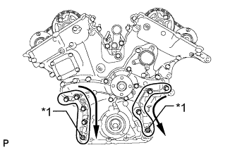
Fully tighten the 12 bolts shown in the illustration.
- Torque:
- 21 N*m { 214 kgf*cm, 15 ft.*lbf }
Tech Tips
Tighten the bolts in order from lower to upper as shown in the illustration.
-
Install the wiring harness clamp bracket with the bolt.
- Torque:
- 10 N*m { 102 kgf*cm, 7 ft.*lbf }
-
-
INSTALL TIMING CHAIN CASE OIL SEAL
-
Apply MP grease to the lip of a new oil seal.
Note
Keep the lip free of foreign matter.
-
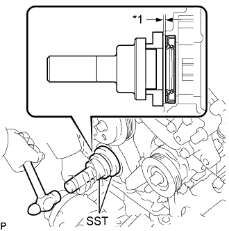
Text in Illustration *1 Depth Using SST and a hammer, tap in the oil seal until its surface is flush with the timing chain case edge.
- SST
- 09223-22010
- 09506-35010
Standard depth 0 to 1.0 mm (0 to 0.0394 in.) Note
-
Keep the lip free of foreign matter.
-
Do not tap the oil seal at an angle.
-
-
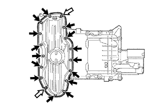
INSTALL CYLINDER HEAD COVER SUB-ASSEMBLY
-
Before applying seal packing black, completely remove any old seal packing adhering to the sealed areas.
-
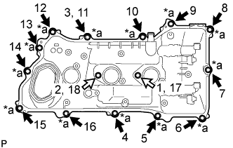
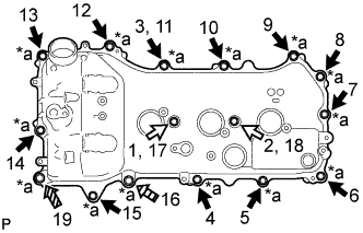
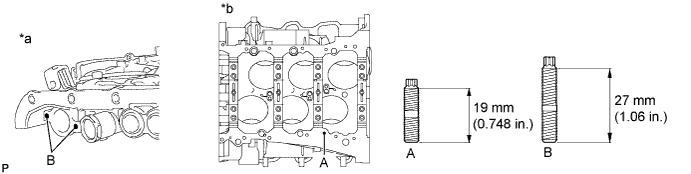
Text in Illustration *1 Seal Packing Black Application Area *a Part Contact Areas *b 4.0 to 10.0 mm (0.157 to 0.394 in.) Clean and degrease the areas where the cylinder head cover, timing chain cover and camshaft housing RH contact each other with brake cleaner or non-residue solvent so that there is no oil, water or other foreign matter adhering to those areas.
Note
The seal packing black cannot be wiped off. It can only be removed with a scraper.
-
Apply seal packing black (diameter: 2.0 to 3.0 mm (0.0787 to 0.118 in.)) to the areas shown in the illustration and install the cylinder head cover.
Seal packing Toyota Genuine Seal Packing Black, Three Bond 1207B or equivalent Note
-
Remove any oil from the contact surface.
-
Install the cylinder head cover within 3 minutes after applying seal packing.
-
Do not start the engine for at least 2 hours after installation.
-
-
Install 5 new gaskets to the camshaft bearing caps.
-
Install a new gasket to the cylinder head cover.
-
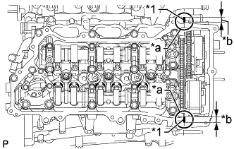
Text in Illustration *a Apply adhesive to these bolts Bolt A Bolt B Apply adhesive to the threads of the 13 bolts shown in the illustration, and then using 2 new seal washers for each bolt, install the cylinder head cover with the 15 bolts.
- Torque:
- 10 N*m { 102 kgf*cm, 7 ft.*lbf }
Adhesive Toyota Genuine Adhesive 1324, Three Bond 1324 or equivalent. Standard Bolt Item Length A 25 mm (0.984 in.) B 60 mm (2.36 in.) -
Attach the clamps and connect the connectors to connect the cylinder head cover.
-
-
INSTALL CYLINDER HEAD COVER SUB-ASSEMBLY LH
-
Before applying seal packing black, completely remove any old seal packing adhering to the sealed areas.
-
Text in Illustration *1 Seal Packing Black Application Area *a Part Contact Areas *b 4.0 to 10.0 mm (0.157 to 0.394 in.) Clean and degrease the areas where the cylinder head cover LH, timing chain cover and camshaft housing LH contact each other with brake cleaner or non-residue solvent so that there is no oil, water or other foreign matter adhering to those areas.
Note
The seal packing black cannot be wiped off. It can only be removed with a scraper.
-
Apply seal packing black (diameter: 2.0 to 3.0 mm (0.0787 to 0.118 in.)) to the areas shown in the illustration and install the cylinder head cover LH.
Seal packing Toyota Genuine Seal Packing Black, Three Bond 1207B or equivalent Note
-
Remove any oil from the contact surface.
-
Install the cylinder head cover LH within 3 minutes after applying seal packing.
-
Do not start the engine for at least 2 hours after installation.
-
-
Install 5 new gaskets to the camshaft bearing caps.
-
Install a new gasket to the cylinder head cover.
-
Text in Illustration *a Apply adhesive to these bolts Bolt A Bolt B Bolt C Bolt D Apply adhesive to the threads of the 14 bolts shown in the illustration, and then using 2 new seal washers for each bolt, install the cylinder head cover LH with the 16 bolts.
- Torque:
- for bolt A and B
- 21 N*m { 214 kgf*cm, 15 ft.*lbf }
- for bolt C and D
- 10 N*m { 102 kgf*cm, 7 ft.*lbf }
Adhesive Toyota Genuine Adhesive 1324, Three Bond 1324 or equivalent. Standard Bolt Item Length A 25 mm (0.984 in.) B 60 mm (2.36 in.) C 35 mm (1.38 in.) D 70 mm (2.76 in.) -
Attach the clamps and connect the connectors to connect the cylinder head cover LH.
-
-
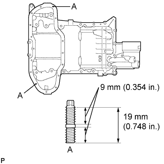
INSTALL OIL STRAINER SUB-ASSEMBLY
-
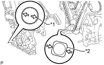
When replacing a stud bolt, install it by using an E6 "TORX" socket wrench, as shown in the illustration.
- Torque:
- 4.0 N*m { 41 kgf*cm, 35 in.*lbf }
Text in Illustration *a Timing Chain Cover *b Cylinder Block Lower -
Install the baffle plate with the 8 bolts.
- Torque:
- 10 N*m { 102 kgf*cm, 7 ft.*lbf }
Tech Tips
Temporarily install the 8 bolts. Tighten the 2 bolts A shown in the illustration before tightening the other bolts.
-
Install a new gasket and the oil strainer with the 3 nuts.
- Torque:
- 10 N*m { 102 kgf*cm, 7 ft.*lbf }
-
Install 2 new O-rings.
-
-
INSTALL OIL PAN SUB-ASSEMBLY
-
When replacing a stud bolt, install it by using an E6 "TORX" socket wrench.
- Torque:
- 4.0 N*m { 41 kgf*cm, 35 in.*lbf }
-
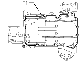
Text in Illustration *1 Seal Packing Apply seal packing in a continuous line as shown in the illustration.
Seal packing Toyota Genuine Seal Packing Black, Three Bond 1207B or equivalent Seal diameter 3.0 to 4.0 mm (0.118 to 0.156 in.) Note
-
Remove any oil from the contact surface.
-
Install the oil pan within 3 minutes after applying seal packing.
-
Do not start the engine for at least 2 hours after installation.
-
-
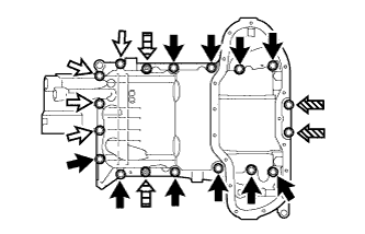
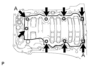
Install the oil pan with the 16 bolts and 2 nuts.
- Torque:
- for bolt A, B and nut
- 21 N*m { 214 kgf*cm, 15 ft.*lbf }
- for bolt C
- 10 N*m { 102 kgf*cm, 7 ft.*lbf }
Standard Bolt Item Length Bolt A 25 mm (0.984 in.) Bolt B 45 mm (1.77 in.) Bolt C 16 mm (0.630 in.) Text in Illustration Bolt A Bolt B Bolt C Nut
-
-
INSTALL NO. 2 OIL PAN SUB-ASSEMBLY
-
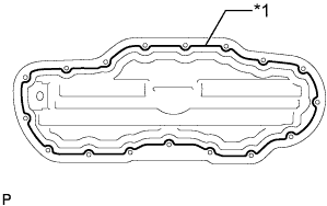
Text in Illustration *1 Seal Packing Apply seal packing in a continuous line as shown in the illustration.
Seal packing Toyota Genuine Seal Packing Black, Three Bond 1207B or equivalent Seal diameter 4.0 to 6.0 mm (0.156 to 0.236 in.) Note
-
Remove any oil from the contact surface.
-
Install the No. 2 oil pan within 3 minutes after applying seal packing.
-
Do not start the engine for at least 2 hours after installation.
-
-
Install the oil pan with the 15 bolts and 2 nuts.
- Torque:
- 10 N*m { 102 kgf*cm, 7 ft.*lbf }
Text in Illustration Bolt Nut
-
-
INSTALL CRANKSHAFT PULLEY
-
Text in Illustration *a Hold *b Turn Align the pulley set key with the key groove of the pulley, and slide on the pulley.
-
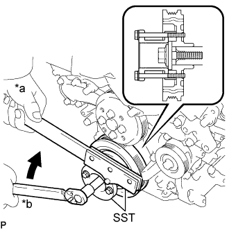
Using SST, install the crankshaft pulley bolt.
- SST
- 09213-70011 ( 09213-70020 )
- 09330-00021
- Torque:
- 250 N*m { 2549 kgf*cm, 184 ft.*lbf }
-
-
INSTALL IGNITION COIL ASSEMBLY
Tech Tips
Perform "Inspection After Repairs" after replacing the ignition coil Click here.
-
for Bank 1:
-
Install the 3 ignition coils with the 3 bolts.
- Torque:
- 10 N*m { 102 kgf*cm, 7 ft.*lbf }
Tech Tips
Perform "Inspection After Repairs" after replacing the ignition coil Click here.
-
Connect the VVT sensor connector and 3 ignition coil connectors to connect the engine wire.
-
Connect the clamp and install the 2 nuts.
- Torque:
- 10 N*m { 102 kgf*cm, 7 ft.*lbf }
-
-
for Bank 2:
-
Install the 3 ignition coils with the 3 bolts.
- Torque:
- 10 N*m { 102 kgf*cm, 7 ft.*lbf }
Tech Tips
Perform "Inspection After Repairs" after replacing the ignition coil Click here.
-
Connect the manifold absolute pressure sensor connector, VVT sensor connector and 3 ignition coil connectors to connect the engine wire.
-
Connect the 2 clamps and install the 3 nuts.
- Torque:
- 10 N*m { 102 kgf*cm, 7 ft.*lbf }
-
-
Connect the inverter reservoir tank assembly with the 2 bolts.
- Torque:
- 13 N*m { 133 kgf*cm, 10 ft.*lbf }
-
for RHD:
Install the inverter bracket to the inverter with the 2 bolts.
- Torque:
- 8.0 N*m { 82 kgf*cm, 71 in.*lbf }
-
for RHD:
Attach the 2 wire harness clamps to the inverter bracket.
-
-
INSTALL WATER INLET ASSEMBLY
-
Install a new No. 1 water inlet housing gasket and water outlet pipe O-ring.
-
Install the water inlet assembly with the 4 bolts and nut.
- Torque:
- 10 N*m { 102 kgf*cm, 7 ft.*lbf }
Note
Be careful not to allow the O-ring to get caught between parts.
-
Connect the 4 hoses.
-
-
INSTALL NO. 2 ENGINE COVER
-
Install the No. 2 engine cover with the 3 clips.
-
Connect the clamp.
-
-
INSTALL INJECTOR DRIVER
Note
-
Be careful not to drop or strike the injector driver.
-
The injector driver is grounded at the bolt and nut. To make sure that it is grounded, clean all oil and foreign matter from the installation areas of the injector driver and engine before installing the injector driver.
-
Install the injector driver with the bolt and 2 nuts.
- Torque:
- 10 N*m { 102 kgf*cm, 7 ft.*lbf }
-
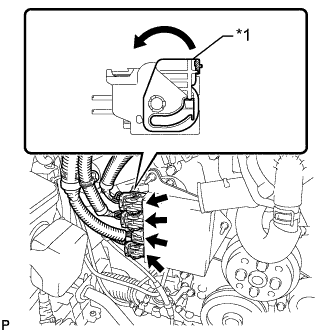
Text in Illustration *1 Lock Lever Connect the 4 connectors to the injector driver. Move the lock levers in the direction indicated by the arrow to lock the 3 connectors.
-
-
INSTALL NO. 1 ENGINE COVER
-
Install the No. 1 engine cover with the 3 clips.
-
-
INSTALL WATER PUMP PULLEY
-
Temporarily install the pulley with the 4 bolts.
-
Using SST, hold the pulley and tighten the 4 bolts.
- SST
- 09960-10010 ( 09962-01000, 09963-00700 )
- Torque:
- 21 N*m { 214 kgf*cm, 15 ft.*lbf }
-
-
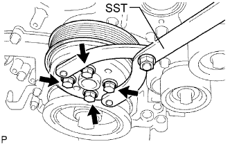
INSTALL V-RIBBED BELT TENSIONER ASSEMBLY
-
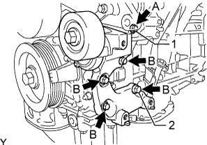
Temporarily install the V-ribbed belt tensioner with the 5 bolts.
Standard Bolt Item Length A 70 mm (2.76 in.) B 35 mm (1.38 in.) -
Install the V-ribbed belt tensioner by tightening the bolt 1 and bolt 2 in the order shown in the illustration.
- Torque:
- 43 N*m { 438 kgf*cm, 32 ft.*lbf }
-
Tighten the other bolts.
- Torque:
- 43 N*m { 438 kgf*cm, 32 ft.*lbf }
-
-
INSTALL FUEL PUMP ASSEMBLY (for High Pressure)
-
INSTALL ENGINE WIRE
-
INSTALL ENGINE ASSEMBLY