OIL PUMP REMOVAL

-
REMOVE ENGINE ASSEMBLY
-
REMOVE ENGINE WIRE
-
REMOVE FUEL PUMP ASSEMBLY (for High Pressure)
-
REMOVE V-RIBBED BELT TENSIONER ASSEMBLY
-
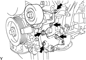
Remove the 5 bolts and V-ribbed belt tensioner.
-
-
REMOVE WATER PUMP PULLEY
-
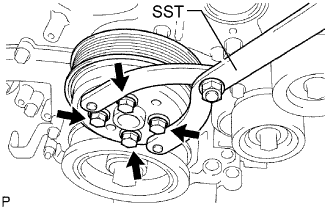
Using SST, hold the water pump pulley.
- SST
- 09960-10010 ( 09962-01000, 09963-00700 )
-
Remove the 4 bolts and water pump pulley.
-
-
REMOVE NO. 1 ENGINE COVER
-
Remove the 3 clips and No. 1 engine cover.
-
-
REMOVE INJECTOR DRIVER
-
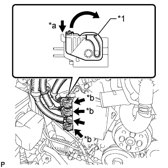
Text in Illustration *1 Lock Lever *a Release *b Lock with Connector Move the lock levers in the direction indicated by the arrow to release the 3 connector locks. Disconnect the 4 connectors from the injector driver.
-
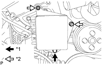
Text in Illustration *1 Bolt *2 Nut Remove the bolt, 2 nuts and injector driver.
Note
Be careful not to drop or strike the injector driver.
-
-
REMOVE NO. 2 ENGINE COVER
-
Remove the 3 clips and clamp, and then remove the No. 2 engine cover.
-
-
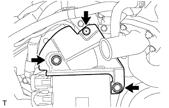
REMOVE WATER INLET ASSEMBLY
-
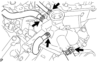
Disconnect the 4 hoses.
-
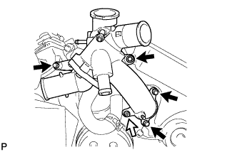
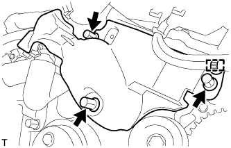
Remove the 4 bolts, nut and water inlet assembly.
Text in Illustration 
Bolt 
Nut -
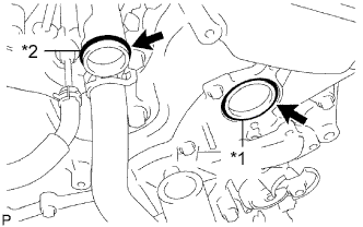
Text in Illustration *1 No. 1 Water Inlet Housing Gasket *2 Water Outlet Pipe O-ring Remove the No. 1 water inlet housing gasket and water outlet pipe O-ring.
-
-
REMOVE CRANKSHAFT PULLEY
-
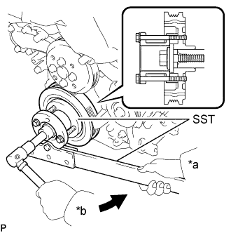
Text in Illustration *a Hold *b Turn Using SST, loosen the pulley bolt.
- SST
- 09213-70011 ( 09213-70020 )
- 09330-00021
-
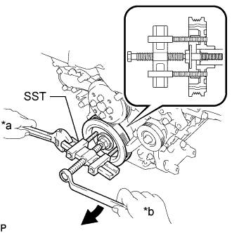
Text in Illustration *a Hold *b Turn Tighten the pulley bolt to 2 or 3 threads of the crankshaft.
-
Using SST, remove the pulley bolt and pulley.
- SST
- 09950-50013 ( 09951-05010, 09952-05010, 09953-05020, 09954-05021 )
Tech Tips
Apply grease to the threads and tip of SST (center bolt) prior to use.
-
-
REMOVE NO. 2 OIL PAN SUB-ASSEMBLY
-
Remove the 15 bolts and 2 nuts.
Text in Illustration Bolt Nut -
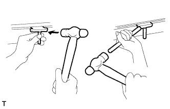
Insert the blade of an oil pan seal cutter between the oil pans. Cut through the applied sealer and remove the No. 2 oil pan.
Note
Be careful not to damage the contact surfaces of the oil pans.
-
-
REMOVE OIL PAN SUB-ASSEMBLY
-
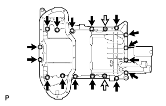
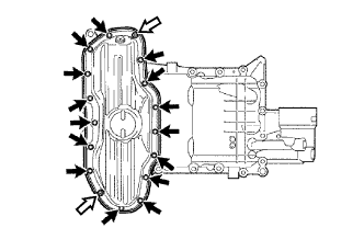
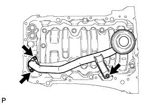
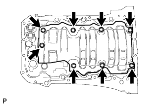
Remove the 16 bolts and 2 nuts.
Text in Illustration Bolt Nut Tech Tips
Be sure to clean the bolts and stud bolts and check the threads for cracks or other damage.
-
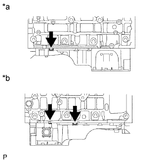
Text in Illustration *a LH Side *b RH Side Remove the oil pan by prying between the oil pan and cylinder block with a screwdriver.
Note
Be careful not to damage the contact surfaces of the cylinder block and oil pan.
Tech Tips
Tape the screwdriver tip before use.
-
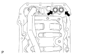
Remove the 2 O-rings.
-
-
REMOVE OIL STRAINER SUB-ASSEMBLY
-
Remove the 3 nuts, oil strainer and gasket.
-
Remove the 8 bolts and baffle plate.
-
-
REMOVE IGNITION COIL ASSEMBLY
-
for RHD:
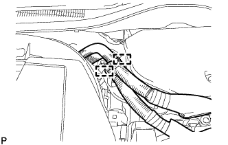
Detach the 2 wire harness clamps from the inverter bracket.
-
for RHD:
Remove the 2 bolts and inverter bracket from the inverter.
-
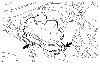
Remove the 2 bolts and disconnect the inverter reservoir tank assembly.
-
for Bank 1:
-
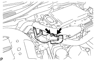
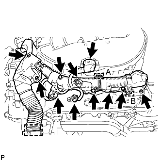
Remove the 3 nuts and disconnect the clamp labeled A using a clip remover. Then, disconnect the clamp labeled B using needle-nose pliers.
Note
Do not damage the claws of the clamp.
-
Disconnect the manifold absolute pressure sensor connector, VVT sensor connector and 3 ignition coil connectors to disconnect the engine wire.
-
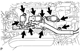
Remove the 3 bolts and 3 ignition coils.
-
-
for Bank 2:
-
Remove the 2 nuts and disconnect the clamp.
-
Disconnect the VVT sensor connector and 3 ignition coil connectors to disconnect the engine wire.
-
Remove the 3 bolts and 3 ignition coils.
-
-
-
REMOVE CYLINDER HEAD COVER SUB-ASSEMBLY LH
-
Detach the clamps and disconnect the connectors to disconnect the wire harness from the cylinder head cover LH.
-
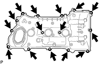
Remove the 16 bolts, cylinder head cover LH and gasket.
-
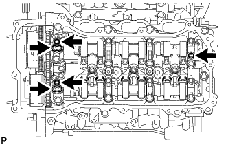
Remove the 5 gaskets.
-
-
REMOVE CYLINDER HEAD COVER SUB-ASSEMBLY
-
Detach the clamps and disconnect the connectors to disconnect the wire harness from the cylinder head cover.
-
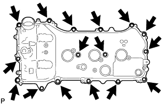
Remove the 15 bolts, cylinder head cover and gasket.
-
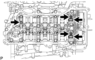
Remove the 5 gaskets.
-
-
REMOVE TIMING CHAIN COVER SUB-ASSEMBLY
-
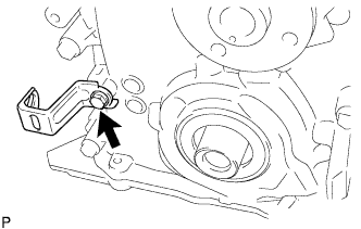
Remove the bolt and wire harness clamp bracket.
-
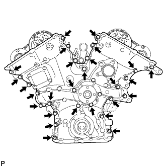
Remove the 25 bolts and 2 nuts shown in the illustration.
-
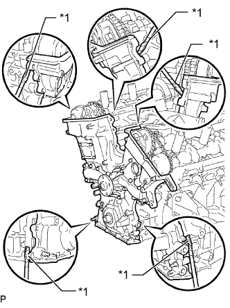
Text in Illustration *1 Protective Tape Remove the timing chain cover by prying between the timing chain cover and cylinder head or cylinder block with a screwdriver.
Note
Be careful not to damage the contact surfaces of the cylinder head, cylinder block and chain cover.
Tech Tips
Tape the screwdriver tip before use.
-
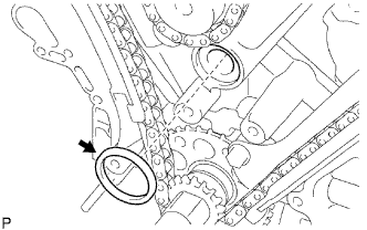
Remove the gasket.
-
-
REMOVE TIMING CHAIN CASE OIL SEAL
-
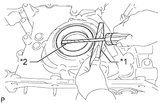
Text in Illustration *1 Wooden Block *2 Protective Tape Using a screwdriver, pry out the oil seal.
Tech Tips
Tape the screwdriver tip before use.
-