OIL PUMP REMOVAL

Note
Do not remove the oil pump or oil pump relief valve from the timing chain cover assembly.
-
REMOVE FUEL PUMP WITH SEAL SUB-ASSEMBLY
-
REMOVE ENGINE MOTOR CABLE CLAMP BRACKET (for LHD)
-
Detach the generator cable and motor cable from the engine motor cable clamp bracket.
-
Remove the bolt and engine motor cable clamp bracket.
-
-
REMOVE FAN AND GENERATOR V BELT
-
Prepare a clean durable piece of cloth and fold it several times.
Tech Tips
Fold the cloth several times to make it thicker.
-
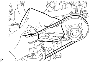
Pass the cloth under the fan and generator V belt between the crankshaft pulley assembly and engine water pump assembly as shown in the illustration.
Note
Position the cloth so that the part closest to the engine is longer.
-
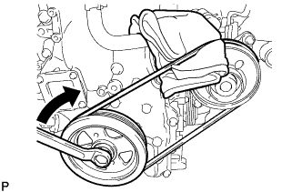
Slightly rotate the crankshaft pulley assembly clockwise so that the cloth is pulled between the fan and generator V belt and engine water pump assembly.
Note
Do not allow the cloth to be pulled further than the top center of the engine water pump assembly.
-
Fold the cloth over the fan and generator V belt and pull it as shown in the illustration while gradually rotating the crankshaft pulley assembly clockwise.
Note
Pull the cloth until the upper part of the fan and generator V belt comes off the engine water pump assembly.
-
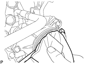
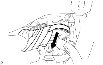
Check that the upper part of the fan and generator V belt is off the engine water pump assembly, then rotate the crankshaft pulley assembly clockwise to remove the fan and generator V belt.
-
-
REMOVE ENGINE UNDER COVER
-
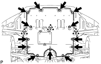
Remove the 13 screws, 3 clips and engine under cover.
-
-
REMOVE FRONT SUSPENSION MEMBER BRACE
-
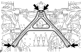
Remove the 4 bolts, turn the clip to loosen it, and remove the front suspension member brace.
Tech Tips
Do not remove the clip from the front suspension member brace.
-
-
REMOVE NO. 2 ENGINE UNDER COVER
-
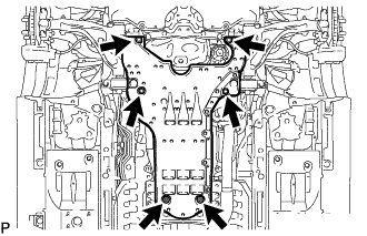
Remove the 4 screws, turn the 2 grommets to loosen them and remove the No. 2 engine under cover.
-
-
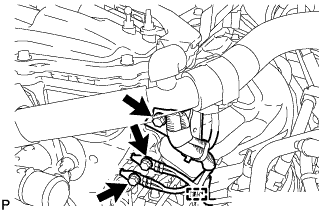
DISCONNECT NO. 1 HV WATER PUMP OUTLET PIPE
-
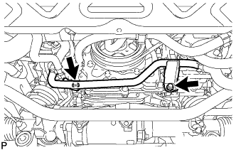
Remove the 2 bolts to disconnect the No. 1 HV water pump outlet pipe from the stiffening crankcase assembly.
-
-
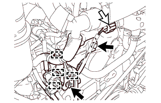
DISCONNECT OIL COOLER TUBE SUB-ASSEMBLY
-
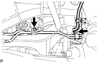
Detach the clamp to disconnect the engine ground wire from the oil cooler tube sub-assembly.
-
Remove the 2 bolts to disconnect the oil cooler tube sub-assembly from the stiffening crankcase assembly.
-
-
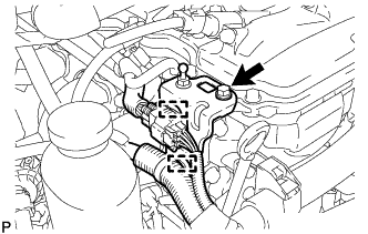
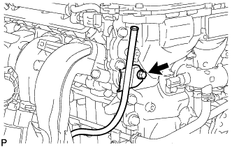
DISCONNECT PCV HOSE ASSEMBLY
-
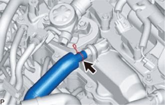
Slide the clamp and disconnect the PCV hose assembly from the PCV valve sub-assembly.
-
-
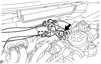
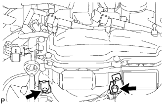
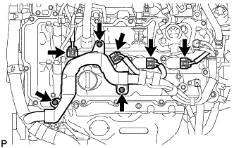
DISCONNECT ENGINE WIRE
-
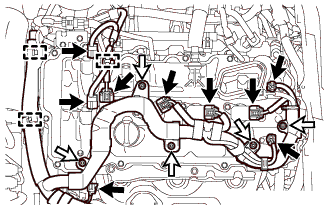
Detach the 3 wire harness clamps.
Text in Illustration 
Connector 
Nut -
Disconnect the 2 camshaft timing oil control valve connectors.
-
Disconnect from the 2 VVT sensor connectors.
-
Disconnect the 4 ignition coil connectors.
-
Disconnect the engine oil pressure switch connector.
-
Remove the 5 nuts to disconnect the engine wire.
-
Detach the 2 wire harness clamps from the wire harness clamp bracket.
-
Remove the bolt and wire harness clamp bracket from the cylinder head cover sub-assembly.
-
Disconnect the 4 wire harness clamps.
Text in Illustration Bolt Connector -
Disconnect the engine coolant temperature sensor connector.
-
Remove the 2 bolts and wire harness clamp bracket from the timing chain cover assembly.
-
Remove the bolt and wire harness clamp bracket from the timing chain cover assembly.
-
Remove the 2 bolts and 2 ground wires from the timing chain cover assembly.
-
Detach the wire harness clamp.
-
-
REMOVE WIRE HARNESS CLAMP BRACKET
-
Remove the 2 bolts and 2 wire harness clamp brackets from the timing chain cover assembly.
-
-
REMOVE IGNITION COIL ASSEMBLY
-
Disconnect the 4 ignition coil assembly connectors.
-
Remove the 3 nuts and disconnect the engine wire from the cylinder head cover sub-assembly.
-
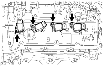
Remove the 4 bolts and 4 ignition coil assemblies from the cylinder head cover sub-assembly.
Note
If an ignition coil assembly has been struck or dropped, replace it.
Tech Tips
Arrange the removed parts in the correct order.
-
-
REMOVE CYLINDER HEAD COVER SUB-ASSEMBLY
-
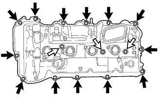
Remove the 16 bolts, 3 seal washers and cylinder head cover sub-assembly from the camshaft housing sub-assembly.
Text in Illustration Bolt Bolt with Seal Washer -
Remove the cylinder head cover gasket from the cylinder head cover sub-assembly.
-
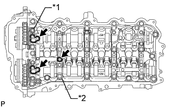
Text in Illustration *1 No. 1 Camshaft Bearing Cap *2 No. 2 Camshaft Bearing Cap Remove the 3 gaskets from the No. 1 camshaft bearing cap and No. 2 camshaft bearing cap.
-
-
REMOVE ENGINE OIL LEVEL DIPSTICK
-
Remove the engine oil level dipstick from the engine oil level dipstick guide.
-
-
REMOVE ENGINE OIL LEVEL DIPSTICK GUIDE
-
Remove the bolt and engine oil level dipstick guide.
-
Remove the O-ring from the engine oil level dipstick guide.
-
-
REMOVE CRANKSHAFT POSITION SENSOR
-
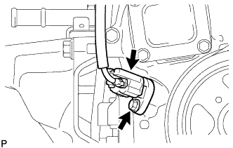
Disconnect the crankshaft position sensor connector.
-
Remove the bolt and crankshaft position sensor from the timing chain cover assembly.
-
-
REMOVE CRANKSHAFT PULLEY ASSEMBLY
-
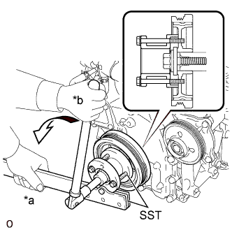
Text in Illustration *a Hold *b Turn Using SST, hold the crankshaft pulley assembly and loosen the crankshaft pulley set bolt. Further loosen the crankshaft pulley set bolt until 2 or 3 threads are screwed into the crankshaft.
- SST
- 09213-54015
- 09330-00021
Tech Tips
SST (Crankshaft pulley holding tool) fixing bolt part No.: 91551-80650 (2 pcs)
-
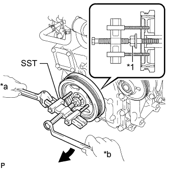
Text in Illustration *1 Crankshaft Pulley Set Bolt *a Hold *b Turn Using SST, remove the crankshaft pulley and crankshaft pulley set bolt.
- SST
- 09950-50013 ( 09951-05010, 09952-05010, 09953-05020, 09954-05011 )
Tech Tips
Apply molybdenum grease to the threads and tip of SST (center bolt) prior to use.
-
-
REMOVE NO. 13 WATER BY-PASS HOSE
-
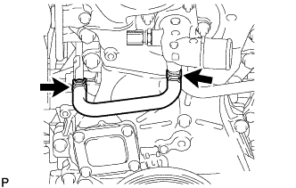
Slide the 2 clamps and remove the No. 13 water by-pass hose from the water outlet sub-assembly and No. 3 water by-pass pipe.
-
-
REMOVE NO. 11 WATER BY-PASS HOSE
-
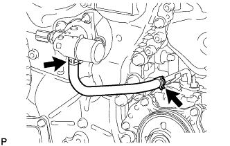
Slide the 2 clamps and remove the No. 11 water by-pass hose from the water outlet sub-assembly and No. 5 water by-pass pipe.
-
-
REMOVE WATER OUTLET SUB-ASSEMBLY
-
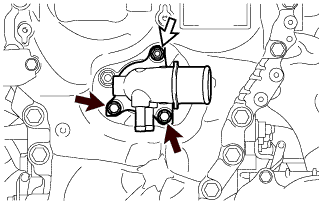
Remove the 2 bolts, nut and water outlet sub-assembly from the timing chain cover assembly.
Text in Illustration Bolt Nut -
Remove the O-ring from the timing chain cover assembly.
-
-
REMOVE TIMING CHAIN COVER ASSEMBLY
-
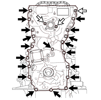
Remove the 19 bolts and 3 nuts from the timing chain cover assembly.
Text in Illustration Bolt Nut -
Remove the timing chain cover assembly by prying between the timing chain cover assembly and camshaft housing sub-assembly, stiffening crankcase assembly, cylinder block sub-assembly or cylinder head sub-assembly with a screwdriver.
Note
Be careful not to damage the contact surfaces of the timing chain cover assembly, camshaft housing sub-assembly, stiffening crankcase assembly, cylinder block sub-assembly and cylinder head sub-assembly.
Tech Tips
Tape the screwdriver tip before use.
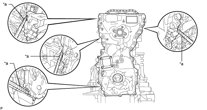
Text in Illustration *a Protective Tape - - -
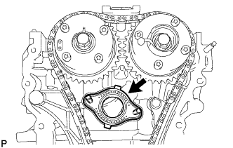
Remove the gasket from the cylinder head sub-assembly.
-
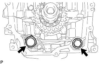
Remove the 2 gaskets from the stiffening crankcase assembly and oil strainer sub-assembly.
-
-
REMOVE TIMING GEAR CASE OR TIMING CHAIN CASE OIL SEAL
-
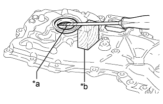
Text in Illustration *a Protective Tape *b Wooden Block Using a screwdriver and wooden block, pry out the timing gear case or timing chain case oil seal.
Note
Do not damage the surface of the timing gear case or timing chain case oil seal press fit hole.
Tech Tips
Tape the screwdriver tip before use.
-