WATER PUMP REMOVAL

-
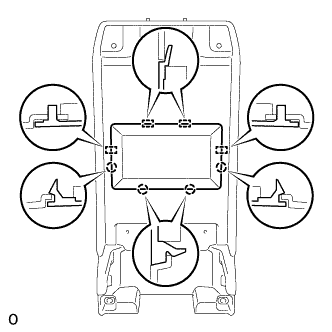
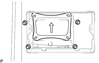
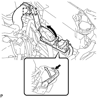
REMOVE V-BANK COVER SUB-ASSEMBLY
-
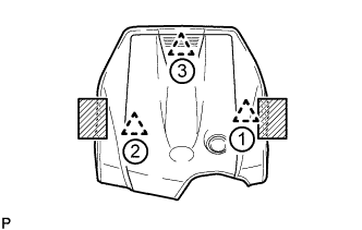
Place both hands on the sides of the cover as shown in the illustration, lift the cover to detach the 2 clips near the front in the order shown in the illustration, and then lift the cover further to detach the rear clip and remove the cover.
Text in Illustration 
Areas to place hands when lifting cover Note
If the cover is lifted rearward or forward and to the right or left at the same time, the cover may be damaged.
-
-
REMOVE ENGINE ROOM SIDE COVER
-
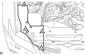
Remove the 4 clips and engine room side cover.
-
-
REMOVE COOL AIR INTAKE DUCT SEAL
-
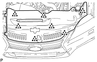
Remove the 7 clips and cool air intake duct seal.
-
-
REMOVE NO. 1 AIR CLEANER INLET
-
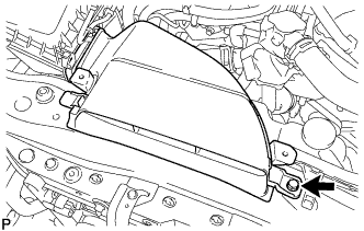
Remove the bolt and No. 1 air cleaner inlet.
-
-
RECOVER REFRIGERANT FROM AIR CONDITIONING SYSTEM
-
Turn the power switch on (READY).
-
Turn the A/C switch on.
-
Operate the air conditioning with a set temperature of 25°C (77°F) and the blower at low for 10 minutes to circulate the refrigerant. This causes most of the compressor oil from the various components of the air conditioning system to collect in the air conditioning compressor.
-
Turn the power switch off.
-
Recover the refrigerant from the air conditioning system using a refrigerant recovery unit.
-
-
DRAIN ENGINE COOLANT
CAUTION:
Do not remove the radiator cap or reservoir tank cap while the engine and radiator are still hot. Pressurized hot engine coolant and steam may be released and cause serious burns.
-
Loosen the radiator drain cock plug.
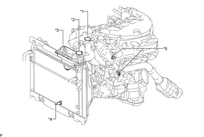
Text in Illustration *1 Radiator Cap *2 Reservoir Tank Cap *3 Radiator Reservoir Tank *4 Radiator Drain Cock Plug *5 Cylinder Block Drain Cock Plug - - -
Remove the reservoir tank cap and drain the coolant.
Tech Tips
Collect the coolant in a container and dispose of it according to the local regulations.
-
Loosen the 2 cylinder block drain cock plugs and drain the coolant from the engine.
-
-
REMOVE LUGGAGE COMPARTMENT FLOOR MAT
-
Remove the luggage compartment floor mat.
-
-
REMOVE LUGGAGE COMPARTMENT TRIM COVER LH
-
Remove the luggage compartment trim cover LH.
-
-
PRECAUTION
Note
After turning the power switch off, waiting time may be required before disconnecting the cable from the negative (-) auxiliary battery terminal. Therefore, make sure to read the disconnecting the cable from the negative (-) auxiliary battery terminal notices before proceeding with work Click here.
-
DISCONNECT CABLE FROM AUXILIARY BATTERY NEGATIVE TERMINAL
Note
When disconnecting the cable, some systems need to be initialized after the cable is reconnected Click here.
-
REMOVE NO. 1 SEAT ARMREST CAP
-
Detach the 4 claws and 4 guides, and remove the No. 1 seat armrest cap.
-
-
REMOVE LOWER HYBRID VEHICLE BATTERY COVER PANEL
CAUTION:
Perform work using insulated gloves and insulated tools.
-
Remove the 4 nuts and lower hybrid vehicle battery cover panel.
-
-
REMOVE SERVICE PLUG GRIP
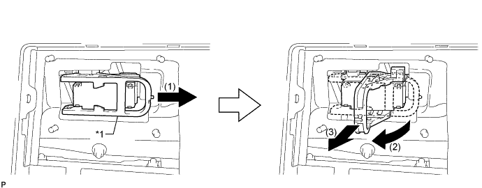
Text in Illustration *1 Lever - -
-
Remove the service plug grip in the order shown in the illustration.
CAUTION:
-
Wear insulated gloves.
-
Remove the service plug grip to interrupt a high voltage circuit at the time of the check.
-
Keep the removed service plug grip in your pocket to prevent other technicians from accidentally reconnecting it while you are servicing the vehicle.
-
After disconnecting the service plug grip, wait for at least 10 minutes before touching any of the high-voltage connectors or terminals.
-
Never turn the power switch on (READY) with the service plug grip removed as malfunctions may occur.
Tech Tips
-
Waiting for at least 10 minutes is required to discharge the high-voltage capacitor inside the inverter with converter assembly.
-
High voltage wiring connectors are orange.
-
Slide the lever and release the lock.
-
Raise the lever and pull the service plug grip to remove it.
-
-
-
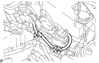
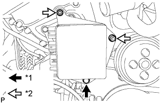
REMOVE ECM
-
Disconnect the 2 ECM connectors and wire harness clamp.
-
Push in the locks on the 2 levers, raise the levers, and disconnect the 2 ECM connectors.
Note
After disconnecting the connectors, make sure that dirt, water or other foreign matter does not contact the connecting part of the connectors.
-
-

for LHD:
Disconnect the clamp.
-
for RHD:
Disconnect the 2 clamps.
-
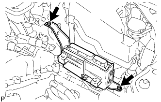
Remove the 2 nuts and ECM.
-
-
REMOVE FAN AND GENERATOR V BELT
-
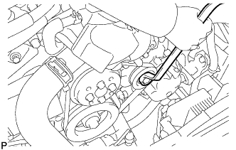
While releasing the belt tension by turning the belt tensioner counterclockwise, remove the fan and generator V belt from the belt tensioner.
-
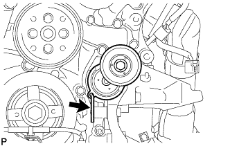
While turning the belt tensioner counterclockwise, align its holes, and then insert the 5 mm bi-hexagon wrench into the holes to secure the belt tensioner.
-
-
REMOVE ENGINE UNDER COVER
-
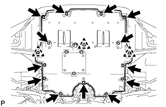
Remove the 13 screws, 3 clips and engine under cover.
-
-
REMOVE REAR ENGINE UNDER COVER LH
-
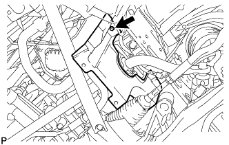
Remove the screw and rear engine under cover LH.
-
-
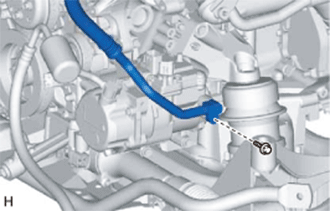
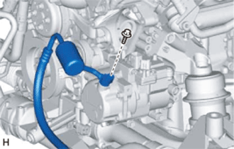
DISCONNECT SUCTION HOSE
-
Remove the bolt and disconnect the suction hose from the compressor with motor assembly.
-
Remove the O-ring from the suction hose.
Note
Seal the openings of the disconnected parts using vinyl tape to prevent moisture and foreign matter from entering them.
-
-
DISCONNECT NO. 1 COOLER REFRIGERANT DISCHARGE HOSE
-
Remove the bolt and disconnect the No. 1 cooler refrigerant discharge hose from the compressor with motor assembly.
-
Remove the O-ring from the No. 1 cooler refrigerant discharge hose.
Note
Seal the openings of the disconnected parts using vinyl tape to prevent moisture and foreign matter from entering them.
-
-
REMOVE COMPRESSOR WITH MOTOR ASSEMBLY
-
Disconnect the connector.
-
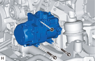
Remove the 2 bolts and nut.
-
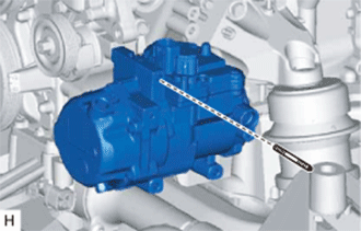
Using an E8 "TORX" socket, remove the stud bolt and compressor with motor assembly.
-
-
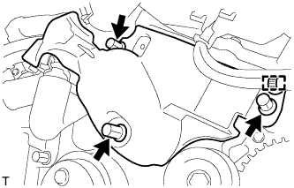
REMOVE V-RIBBED BELT TENSIONER ASSEMBLY
-
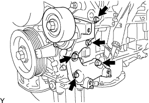
Remove the 5 bolts and V-ribbed belt tensioner.
-
-
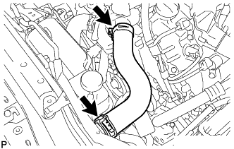
REMOVE NO. 1 RADIATOR HOSE
-
DISCONNECT NO. 2 RADIATOR HOSE
-
Disconnect the No. 2 radiator hose from the water inlet with thermostat sub-assembly.
-
-
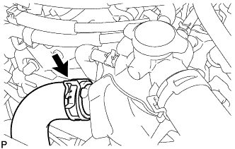
REMOVE NO. 1 ENGINE COVER
-
Remove the 3 clips and No. 1 engine cover.
-
-
REMOVE INJECTOR DRIVER
-
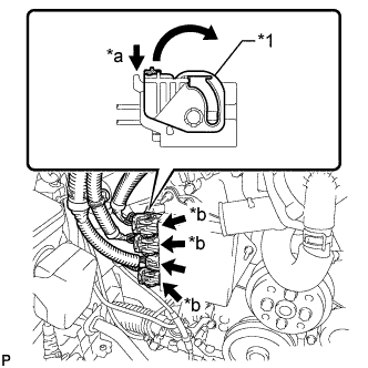
Text in Illustration *1 Lock Lever *a Release *b Lock with Connector Move the lock levers in the direction indicated by the arrow to release the 3 connector locks. Disconnect the 4 connectors from the injector driver.
-
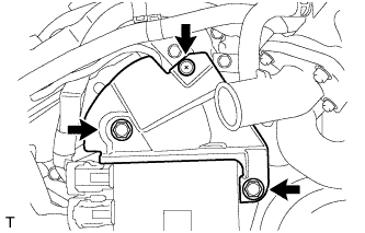
Text in Illustration *1 Bolt *2 Nut Remove the bolt, 2 nuts and injector driver.
Note
Be careful not to drop or strike the injector driver.
-
-
REMOVE NO. 2 ENGINE COVER
-
Remove the 3 clips and clamp, and then remove the No. 2 engine cover.
-
-
REMOVE WATER PUMP PULLEY
-
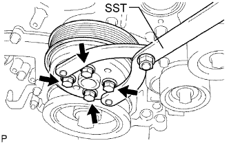
Using SST, hold the water pump pulley.
- SST
- 09960-10010 ( 09962-01000, 09963-00700 )
-
Remove the 4 bolts and water pump pulley.
-
-
REMOVE WATER INLET ASSEMBLY
-
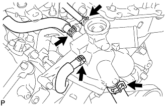
Disconnect the 4 hoses.
-
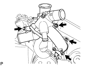
Remove the 4 bolts, nut and water inlet assembly.
Text in Illustration 
Bolt 
Nut -
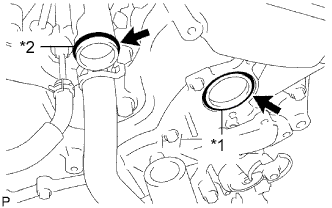
Text in Illustration *1 No. 1 Water Inlet Housing Gasket *2 Water Outlet Pipe O-ring Remove the No. 1 water inlet housing gasket and water outlet pipe O-ring.
-
-
REMOVE ENGINE WATER PUMP ASSEMBLY
-
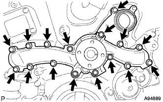
Remove the 16 bolts, engine water pump and water pump gasket.
-