EXHAUST MANIFOLD INSTALLATION

-
INSTALL AIR FUEL RATIO SENSOR
-
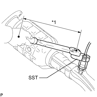
Text in Illustration *1 Fulcrum Length for Bank 2 Sensor 1:
Using SST, install the air fuel ratio sensor to the exhaust manifold LH.
- SST
- 09224-00010
- Torque:
- without SST
- 44 N*m { 449 kgf*cm, 32 ft.*lbf }
- with SST
- 40 N*m { 408 kgf*cm, 30 ft.*lbf }
Tech Tips
-
Use a torque wrench with a fulcrum length of 300 mm (11.8 in.). When using a torque wrench with a fulcrum length that is not 300 mm (11.8 in.), calculate the torque specification for the torque wrench and SST based on the "without SST" torque specification Click here.
-
Make sure SST and the wrench are connected in a straight line.
-
Perform "Inspection After Repairs" after replacing the air fuel ratio sensor Click here.
-
Connect the connector.
-
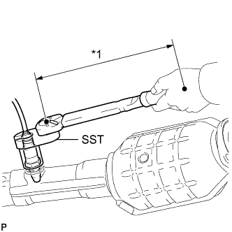
Text in Illustration *1 Fulcrum Length for Bank 1 Sensor 1:
Using SST, install the air fuel ratio sensor to the exhaust manifold RH.
- SST
- 09224-00010
- Torque:
- without SST
- 44 N*m { 449 kgf*cm, 32 ft.*lbf }
- with SST
- 40 N*m { 408 kgf*cm, 30 ft.*lbf }
Tech Tips
-
Use a torque wrench with a fulcrum length of 300 mm (11.8 in.). When using a torque wrench with a fulcrum length that is not 300 mm (11.8 in.), calculate the torque specification for the torque wrench and SST based on the "without SST" torque specification Click here.
-
Make sure SST and the wrench are connected in a straight line.
-
Perform "Inspection After Repairs" after replacing the air fuel ratio sensor Click here.
-
Connect the connector.
-
-
INSTALL EXHAUST MANIFOLD SUB-ASSEMBLY LH
-
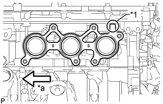
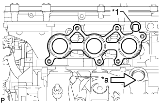
Text in Illustration *1 Protrusion *a Front Install a new gasket as shown in the illustration.
-
Text in Illustration *a Front Temporarily install the exhaust manifold sub-assembly LH with 6 new nuts.
-
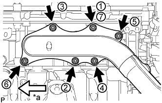
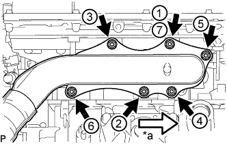
Tighten the 6 nuts in the sequence shown in the illustration.
- Torque:
- 21 N*m { 214 kgf*cm, 15 ft.*lbf }
Note
-
When installing the exhaust manifold, make sure that the flange surface of the exhaust manifold is pressed against the engine and install the nuts in the order shown in the illustration. Make sure to tighten the nut that was tightened first twice at the end.
-
Make sure that the exhaust manifold is correctly fitted onto the stud bolts.
-
Connect the air fuel ratio sensor connector and attach the clamp.
-
-
INSTALL EXHAUST MANIFOLD SUB-ASSEMBLY RH
-
Text in Illustration *1 Protrusion *a Front Install a new gasket as shown in the illustration.
-
Text in Illustration *a Front Temporarily install the exhaust manifold sub-assembly RH with 6 new nuts.
-
Tighten the 6 nuts in the sequence shown in the illustration.
- Torque:
- 21 N*m { 214 kgf*cm, 15 ft.*lbf }
Note
-
When installing the exhaust manifold, make sure that the flange surface of the exhaust manifold is pressed against the engine and install the nuts in the order shown in the illustration. Make sure to tighten the nut that was tightened first twice at the end.
-
Make sure that the exhaust manifold is correctly fitted onto the stud bolts.
-
Connect the air fuel ratio sensor connector and attach the clamp.
-
-
INSTALL NO. 1 EXHAUST PIPE SUPPORT BRACKET SUB-ASSEMBLY
-
Install the No. 1 exhaust pipe support bracket sub-assembly with the 2 bolts.
- Torque:
- 43 N*m { 438 kgf*cm, 32 ft.*lbf }
-
-
INSTALL FRONT EXHAUST PIPE ASSEMBLY
-
w/ Towing Package:
Tech Tips
Only perform this procedure when replacement of the front No. 1 exhaust pipe protector is necessary.
-
Install the front No. 1 exhaust pipe protector and exhaust pipe protector stay with the 2 bolts and 2 nuts.
- Torque:
- 11 N*m { 107 kgf*cm, 8 ft.*lbf }
-
Install the clamp with the bolt.
- Torque:
- 11 N*m { 107 kgf*cm, 8 ft.*lbf }
-
-
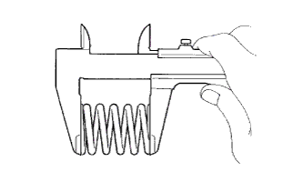
Using a vernier caliper, measure the free length of the compression springs.
Minimum free length 38.5 mm (1.52 in.) Tech Tips
If the free length is less than the minimum, replace the compression spring.
-
Install 2 new gaskets to the front exhaust pipe assembly.
-
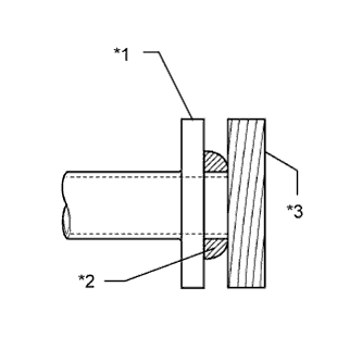
Text in Illustration *1 Front Exhaust Pipe Assembly *2 Gasket *3 Wooden Block Using a plastic-faced hammer and wooden block, tap in a new gasket until its surface is flush with the front exhaust pipe assembly.
Note
-
Be careful with the installation direction of the gasket.
-
Do not reuse the gasket.
-
Do not damage the gasket.
-
Do not push in the gasket by using the exhaust pipe when connecting it.
-
-
Install 2 new gaskets and the front exhaust pipe with 4 new nuts, the 8 bolts, and the 4 compression springs.
- Torque:
- for exhaust manifold side
- 39 N*m { 398 kgf*cm, 29 ft.*lbf }
- for tailpipe side
- 43 N*m { 438 kgf*cm, 32 ft.*lbf }
-
-
CONNECT HEATED OXYGEN SENSOR (for Bank 2 Sensor 2)
-
Connect the heated oxygen sensor connector.
-
-
CONNECT HEATED OXYGEN SENSOR (for Bank 1 Sensor 2)
-
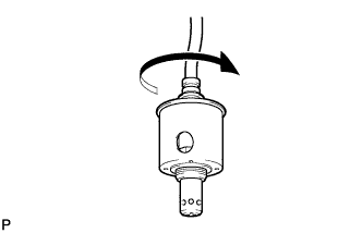
Before installing the heated oxygen sensor, twist the sensor wire counterclockwise 4 turns.
-
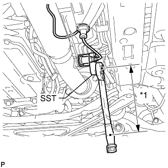
Text in Illustration *1 Fulcrum Length Using SST, connect the heated oxygen sensor to the front exhaust pipe assembly.
- SST
- 09224-00010
- Torque:
- without SST
- 44 N*m { 449 kgf*cm, 32 ft.*lbf }
- with SST
- 40 N*m { 408 kgf*cm, 30 ft.*lbf }
Tech Tips
-
Use a torque wrench with a fulcrum length of 300 mm (11.8 in.). When using a torque wrench with a fulcrum length that is not 300 mm (11.8 in.), calculate the torque specification for the torque wrench and SST based on the "without SST" torque specification Click here.
-
Make sure SST and the wrench are connected in a straight line.
-
After installing the sensor, check that the sensor wire is not twisted.
If the sensor wire is twisted, reinstall the sensor.
-
Connect the grommet of the heated oxygen sensor.
-
-
INSTALL FRONT CENTER FLOOR BRACE
-
Install the front center floor brace and tighten the 2 clips.
-
Install the 6 bolts and 2 nuts.
- Torque:
- 19 N*m { 194 kgf*cm, 14 ft.*lbf }
-
-
INSTALL NO. 2 REAR FLOOR BOARD SUB-ASSEMBLY
-
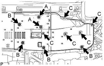
Push in the 2 clips labeled A in the illustration in the upward direction of the vehicle and install the No. 2 rear floor board sub-assembly.
-
Tighten the 4 clips labeled B in the illustration.
-
Install the 5 clips labeled C in the illustration.
-
-
INSTALL NO. 1 REAR FLOOR BOARD SUB-ASSEMBLY
-
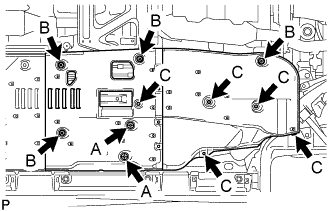
Push in the 2 clips labeled A in the illustration in the upward direction of the vehicle and install the No. 1 rear floor board sub-assembly.
-
Tighten the 4 clips labeled B in the illustration.
-
Install the 5 clips labeled C in the illustration.
-
-
INSTALL NO. 2 OIL LEVEL DIPSTICK GUIDE
-
Install a new O-ring to the No. 2 oil level dipstick guide.
-
Install the No. 2 oil level dipstick guide with the bolt.
- Torque:
- 21 N*m { 214 kgf*cm, 15 ft.*lbf }
-
Install the oil level dipstick.
-
-
INSTALL NO. 1 INVERTER COOLING PIPE (for LHD)
-
Install the No. 1 inverter cooling pipe with the bolt.
- Torque:
- 13 N*m { 127 kgf*cm, 9 ft.*lbf }
-
Connect the 2 hoses.
-
Connect the 2 connectors and 2 wire harness clamps.
-
-
CONNECT AIR CONDITIONING HARNESS
-
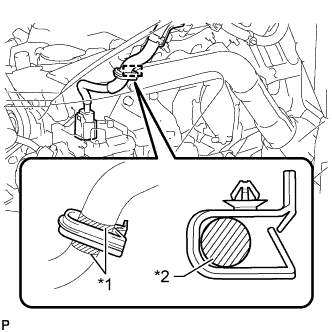
Text in Illustration *1 White Tape *2 Air Conditioning Harness Connect the white tape part of the air conditioning harness to the clamp as shown in the illustration.
Note
Make sure that the air conditioning harness is securely connected.
-
Connect the 2 wire harness clamps to each bracket.
-
Connect the bracket with the bolt.
- Torque:
- 10 N*m { 102 kgf*cm, 7 ft.*lbf }
-
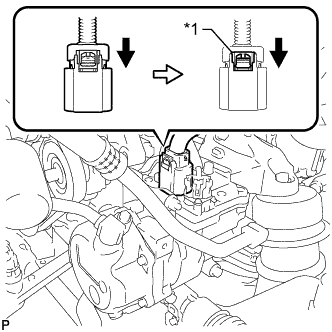
Text in Illustration *1 Green-colored Lock Connect the connector and lock the green-colored lock as shown in the illustration.
CAUTION:
Wear insulated gloves when performing the procedure.
-
-
INSTALL INVERTER RESERVOIR TANK ASSEMBLY (for LHD)
-
Install the inverter reservoir tank assembly with the 2 bolts.
- Torque:
- 13 N*m { 133 kgf*cm, 10 ft.*lbf }
-
Connect the No. 3 inverter cooling hose and No. 4 inverter cooling hose.
-
-
CONNECT NO. 3 ENGINE ROOM RELAY BLOCK
-
INSTALL SKID CONTROL ECU ASSEMBLY
-
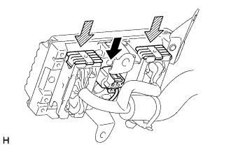
Connect the 2 connectors and press the lock levers down to lock the connectors.
Note
Make sure that the lock levers securely lock the connectors.
-
Connect the connector.
-
Install the skid control ECU assembly with the 2 nuts and bolt.
- Torque:
- 8.5 N*m { 87 kgf*cm, 75 in.*lbf }
-
Connect the clamp to the skid control ECU assembly.
-
-
INSTALL NO. 5 INVERTER BRACKET
-
Install the No. 5 inverter bracket with the 3 bolts.
- Torque:
- 8.0 N*m { 82 kgf*cm, 71 in.*lbf }
-
for LHD:
Connect the No. 4 floor wire with the nut.
- Torque:
- 8.0 N*m { 82 kgf*cm, 71 in.*lbf }
-
-
INSTALL WIRE HARNESS CLAMP BRACKET A (for RHD)
-
Install the wire harness clamp bracket A with the 2 nuts.
- Torque:
- 5.5 N*m { 56 kgf*cm, 49 in.*lbf }
-
-
INSTALL ECM
-
Install the ECM with the 2 nuts.
- Torque:
- 12 N*m { 122 kgf*cm, 9 ft.*lbf }
Note
Any parts that have scratches, dents, etc., or that are dropped or subjected to a strong impact during servicing need to be replaced with new one.
-
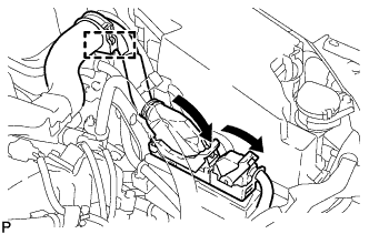
Connect the 2 ECM connectors and wire clamp.
Note
-
When connecting the connectors, make sure that dirt, water or other foreign matter does not become stuck between the connectors and other parts.
-
Make sure that the 2 levers are securely locked.
-
-
for LHD:
Connect the clamp.
-
for RHD:
Connect the 2 clamps.
-
-
INSTALL AIR CLEANER CASE SUB-ASSEMBLY
-
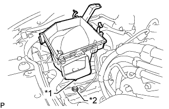
Text in Illustration *1 Pin *2 Grommet Insert the pin on the lower side of the air cleaner case into the grommet.
-
Install the air cleaner case, 2 clamps and 2 bolts.
- Torque:
- 5.0 N*m { 51 kgf*cm, 44 in.*lbf }
Note
During removal, do not lose the grommet on the underside of the air cleaner case.
-
-
INSTALL AIR CLEANER FILTER ELEMENT SUB-ASSEMBLY
-
INSTALL AIR CLEANER CAP WITH AIR CLEANER HOSE
-
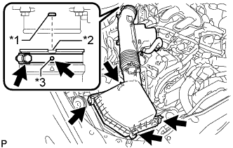
Text in Illustration *1 Bump *2 Cutout *3 Protrusion Install the air cleaner cap with air cleaner hose assembly with the 4 clamps and hose clamp.
- Torque:
- 4.0 N*m { 41 kgf*cm, 35 in.*lbf }
Note
-
Insert the protrusion on the throttle body side hose into the hole of the hose clamp.
-
Align the bump on the throttle body side with the cutout in the hose.
-
Connect the VSV hose to the air cleaner hose.
-
Connect the mass air flow meter connector and clamp to the air cleaner.
-
-
INSTALL POWER STEERING ECU ASSEMBLY
-
Connect the 3 connectors to the power steering ECU.
-
Return the lock lever of each connector to its original position and attach the 2 claws.
Note
Make sure the claws of the lock levers are securely attached.
-
Install the power steering ECU to the battery tray with the 2 bolts.
- Torque:
- 14 N*m { 138 kgf*cm, 10 ft.*lbf }
-
-
INSTALL INVERTER WITH CONVERTER ASSEMBLY
-
INSPECT FOR EXHAUST GAS LEAK
Tech Tips
If an exhaust gas leak has been repaired, perform an inspection following the repair Click here.
If gas is leaking, tighten the areas necessary to stop the leak. Replace damaged parts as necessary.