EXHAUST MANIFOLD REMOVAL

-
REMOVE INVERTER WITH CONVERTER ASSEMBLY
-
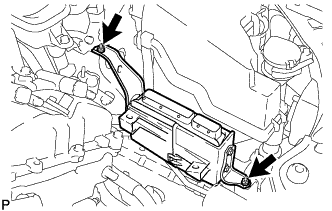
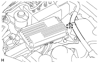
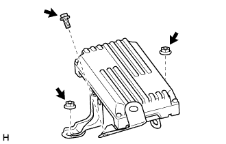
REMOVE POWER STEERING ECU ASSEMBLY
-
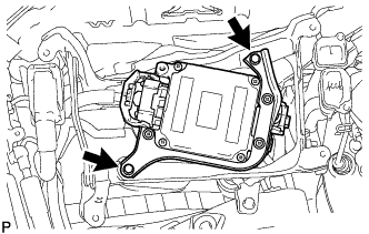
Remove the 2 bolts.
-
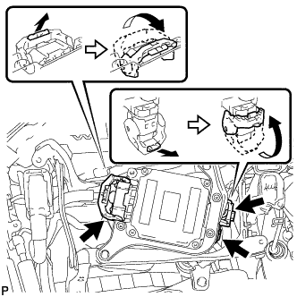
Disconnect the 3 connectors from the power steering ECU.
Tech Tips
Detach the 2 claws, press down the 2 levers, and then disconnect the 2 connectors.
-
-
REMOVE AIR CLEANER CAP WITH AIR CLEANER HOSE
-
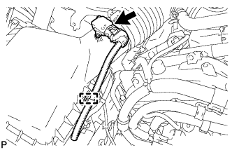
Disconnect the mass air flow meter connector.
-
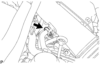
Disconnect the clamp from the air cleaner.
-
Disconnect the VSV hose.
-
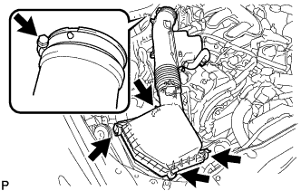
Disconnect the 4 clamps.
-
Remove the hose clamp and air cleaner cap with air cleaner hose.
-
-
REMOVE AIR CLEANER FILTER ELEMENT SUB-ASSEMBLY
-
REMOVE AIR CLEANER CASE SUB-ASSEMBLY
-
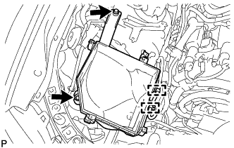
Remove the 2 bolts, 2 clamps and air cleaner case sub-assembly.
Note
When removing the air cleaner case sub-assembly, be careful not to lose the grommet on the underside of the air cleaner case.
-
-
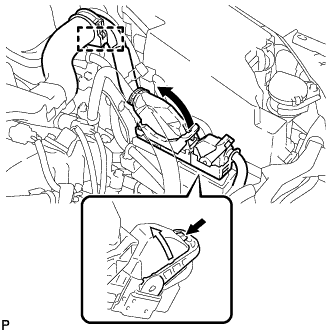
REMOVE ECM
-
Disconnect the 2 ECM connectors and wire harness clamp.
-
Push in the locks on the 2 levers, raise the levers, and disconnect the 2 ECM connectors.
Note
After disconnecting the connectors, make sure that dirt, water or other foreign matter does not contact the connecting part of the connectors.
-
-

for LHD:
Disconnect the clamp.
-
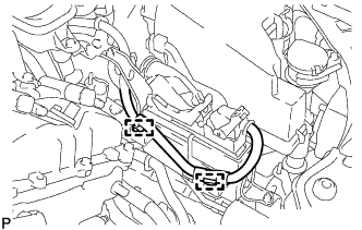
for RHD:
Disconnect the 2 clamps.
-
Remove the 2 nuts and ECM.
-
-
REMOVE WIRE HARNESS CLAMP BRACKET A (for RHD)
-
Remove the 2 nuts and wire harness clamp bracket A.
-
-
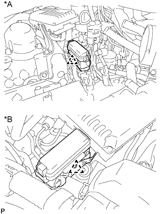
REMOVE NO. 5 INVERTER BRACKET
-
for LHD:
Remove the nut and disconnect the No. 4 floor wire.
-
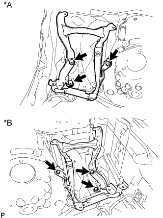
Text in Illustration *A for RHD *B for LHD Remove the 3 bolts and No. 5 inverter bracket.
-
-
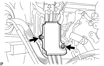
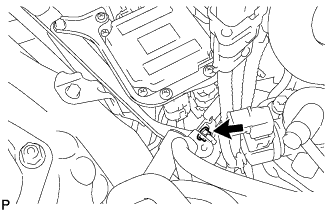
REMOVE SKID CONTROL ECU ASSEMBLY
-
Disconnect the clamp from the skid control ECU assembly.
-
Remove the 2 nuts, bolt and skid control ECU assembly.
-
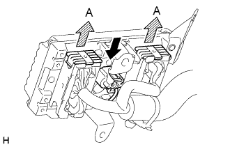
Pull the 2 lock levers upward to release the locks and disconnect the 2 connectors (labeled A).
-
Disconnect the connector.
-
-
DISCONNECT NO. 3 ENGINE ROOM RELAY BLOCK
Text in Illustration *A for RHD *B for LHD -
REMOVE INVERTER RESERVOIR TANK ASSEMBLY (for LHD)
-
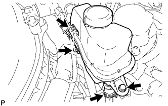
Disconnect the No. 3 inverter cooling hose and No. 4 inverter cooling hose.
-
Remove the 2 bolts and inverter reservoir tank assembly.
-
-
DISCONNECT AIR CONDITIONING HARNESS
-
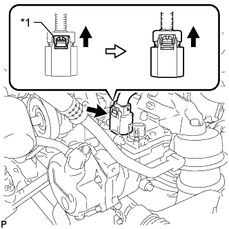
Text in Illustration *1 Green-colored Lock Release the green-colored lock and disconnect the connector as shown in the illustration.
CAUTION:
Wear insulated gloves when performing the procedure.
Note
Insulate the connector by sealing it with tape.
-
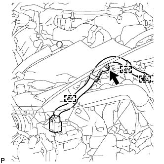
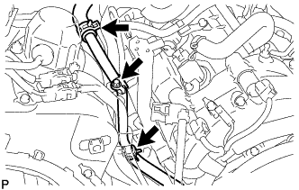
Remove the bolt and 3 wire harness clamps to disconnect the air conditioning harness.
-
-
REMOVE NO. 1 INVERTER COOLING PIPE (for LHD)
-
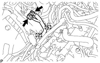
Disconnect the 2 connectors, 2 wire harness clamps and wire harness.
-
Remove the bolt and disconnect the 2 hoses to remove the No. 1 inverter cooling pipe.
-
-
REMOVE NO. 2 OIL LEVEL DIPSTICK GUIDE
-
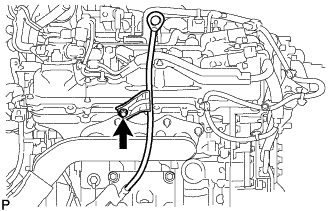
Remove the oil level dipstick.
-
Remove the bolt and No. 2 oil level dipstick guide.
-
Remove the O-ring from the No. 2 oil level dipstick guide.
-
-
REMOVE NO. 1 REAR FLOOR BOARD SUB-ASSEMBLY
-
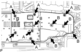
Remove the 5 clips labeled B in the illustration.
-
Loosen the 6 clips labeled A in the illustration and remove the No. 1 rear floor board sub-assembly.
-
-
REMOVE NO. 2 REAR FLOOR BOARD SUB-ASSEMBLY
-
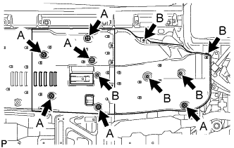
Remove the 5 clips labeled B in the illustration.
-
Loosen the 6 clips labeled A in the illustration and remove the No. 2 rear floor board sub-assembly.
-
-
REMOVE FRONT CENTER FLOOR BRACE
-
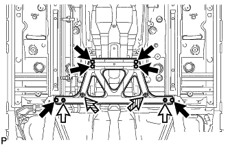
Remove the 6 bolts and 2 nuts.
Text in Illustration 
Bolt 
Nut 
Clip -
Loosen the 2 clips and remove the front center floor brace.
-
-
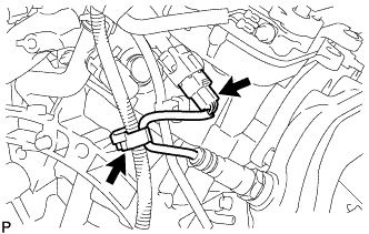
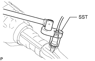
DISCONNECT HEATED OXYGEN SENSOR (for Bank 1 Sensor 2)
-
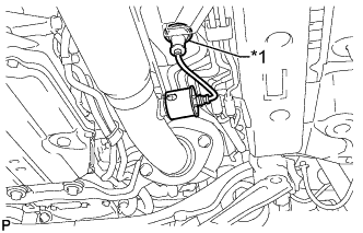
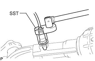
Text in Illustration *1 Grommet Disconnect the grommet of the heated oxygen sensor.
-
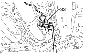
Using SST, disconnect the heated oxygen sensor.
- SST
- 09224-00010
-
-
DISCONNECT HEATED OXYGEN SENSOR (for Bank 2 Sensor 2)
-
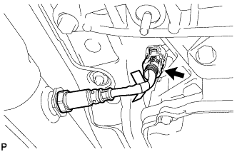
Disconnect the heated oxygen sensor connector.
-
-
REMOVE FRONT EXHAUST PIPE ASSEMBLY
-
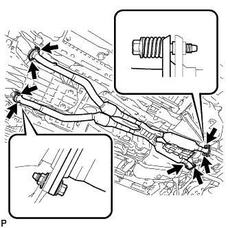
Remove the 4 nuts, 8 bolts, 4 compression springs and front exhaust pipe assembly.
-
Remove the 4 gaskets.
-
w/ Towing Package:
Tech Tips
Only perform this procedure when replacement of the front No. 1 exhaust pipe protector is necessary.
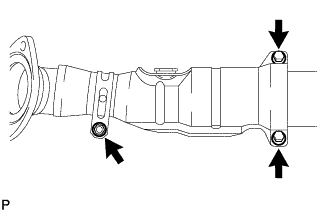
-
Remove the bolt and clamp.
-
Remove the 2 bolts, 2 nuts, exhaust pipe protector stay and front No. 1 exhaust pipe protector.
-
-
-
REMOVE NO. 1 EXHAUST PIPE SUPPORT BRACKET SUB-ASSEMBLY
-
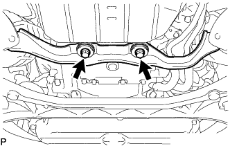
Remove the 2 bolts and No. 1 exhaust pipe support bracket sub-assembly.
-
-
REMOVE EXHAUST MANIFOLD SUB-ASSEMBLY RH
-
Detach the clamp and disconnect the air fuel ratio sensor connector.
-
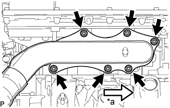
Text in Illustration *a Front Remove the 6 nuts, exhaust manifold sub-assembly RH and gasket.
-
-
REMOVE EXHAUST MANIFOLD SUB-ASSEMBLY LH
-
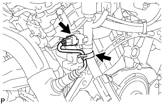
Detach the clamp and disconnect the air fuel ratio sensor connector.
-
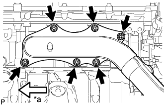
Text in Illustration *a Front Remove the 6 nuts, exhaust manifold sub-assembly LH and gasket.
-
-
REMOVE AIR FUEL RATIO SENSOR
-
for Bank 1 Sensor 1:
Using SST, remove the air fuel ratio sensor.
- SST
- 09224-00010
-
for Bank 2 Sensor 1:
Using SST, remove the air fuel ratio sensor.
- SST
- 09224-00010
-