INTAKE MANIFOLD INSTALLATION

-
INSTALL STUD BOLT
Note
If a stud bolt is deformed or its threads are damaged, replace it.
-
Using the E6 and E8 "TORX" socket wrench, install the stud bolts.
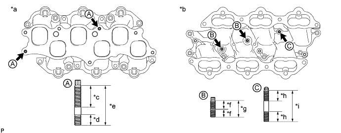
Text in Illustration *a Upper Side *b Lower Side *c 26 mm (1.02 in.) *d 13 mm (0.512 in.) *e 48 mm (1.89 in.) *f 9 mm (0.354 in.) *g 19 mm (0.748 in.) *h 12 mm (0.472 in.) *i 37 mm (1.46 in.) - - - Torque:
- for stud bolt A
- 10 N*m { 102 kgf*cm, 7 ft.*lbf }
- for stud bolt B and C
- 4.0 N*m { 41 kgf*cm, 35 in.*lbf }
-
-
INSTALL WIRE HARNESS
-
Install the wire harness with the bolt.
- Torque:
- 10 N*m { 102 kgf*cm, 7 ft.*lbf }
-
Attach the 2 clamps.
-
-
INSTALL SOLENOID VALVE ASSEMBLY
-
Install 2 new O-rings to the solenoid valve assembly.
-
Install the solenoid valve assembly to the No. 4 fuel pipe sub-assembly, and then install the No. 3 fuel pipe assembly.
Note
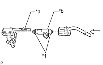
Make sure that the protrusion of the solenoid valve assembly is securely fit into the groove of the No. 4 fuel pipe sub-assembly.
Text in Illustration *1 O-ring *a Groove *b Protrusion -
Press in the No. 3 fuel pipe sub-assembly and insert the 2 O-rings of the solenoid valve assembly.
Note
-
Push in the O-rings gently, taking care not to deform them.
-
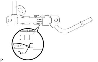
Push in the No. 3 fuel pipe sub-assembly until it contacts the end as shown in the illustration.
Text in Illustration *a Contact -
-
Install the solenoid valve assembly to the intake manifold with the 2 bolts and nut.
- Torque:
- 10 N*m { 102 kgf*cm, 7 ft.*lbf }
-
-
INSTALL INTAKE MANIFOLD
-
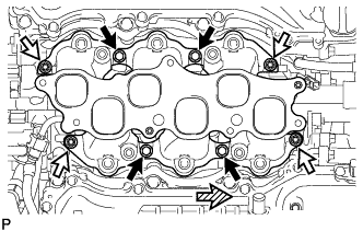
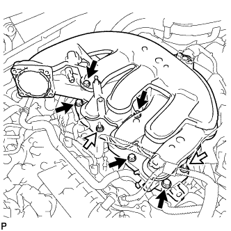
Install 2 new gaskets and the intake manifold with the 4 bolts and 4 nuts.
- Torque:
- 21 N*m { 214 kgf*cm, 15 ft.*lbf }
Text in Illustration 
Bolt 
Nut 
Front -
Install the fuel tube Click here.
-
Apply engine oil to the threads of the union bolt.
-
Install a new gasket to the fuel tube, and then connect the fuel tube to the fuel pump with the union bolt.
- Torque:
- 23 N*m { 235 kgf*cm, 17 ft.*lbf }
-
Attach the connector to the intake manifold.
-
-
INSTALL FUEL DELIVERY PIPE SUB-ASSEMBLY
-
Install 6 new injection vibration insulators to the intake manifold.
-
Install the 4 No. 1 delivery pipe spacers to the intake manifold.
-
Install the delivery pipe sub-assembly (with injector) to the intake manifold.
Note
Be careful not to twist the O-ring.
-
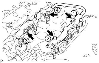
Install the fuel injector assemblies to the fuel delivery pipe sub-assemblies with the 4 bolts in the order shown in the illustration.
- Torque:
- 17 N*m { 173 kgf*cm, 13 ft.*lbf }
-
Connect the 6 injector connectors and 2 clamps.
-
Connect the fuel tube sub-assembly to the fuel delivery pipe sub-assembly Click here.
-
Connect the No. 3 fuel tube sub-assembly to the No. 4 fuel tube sub-assembly Click here.
-
-
INSTALL INTAKE AIR SURGE TANK ASSEMBLY
Note
Do not apply oil to the bolts for the parts listed below:
Part Intake air surge tank assembly and intake manifold No. 2 surge tank stay and intake air surge tank assembly
-
Connect the water by-pass hose clamp.
-
Install a new gasket to the intake air surge tank assembly.
-
Install the intake air surge tank assembly with the 2 nuts and 5 bolts.
- Torque:
- 21 N*m { 214 kgf*cm, 15 ft.*lbf }
Text in Illustration Bolt Nut -
Install the No. 2 surge tank stay with the bolt.
- Torque:
- 21 N*m { 214 kgf*cm, 15 ft.*lbf }
-
Install the No. 3 water by-pass pipe with the bolt.
- Torque:
- 10 N*m { 102 kgf*cm, 7 ft.*lbf }
-
Connect the No. 2 water by-pass hose to the intake air surge tank assembly.
-
Connect the PCV hose.
-
Connect the connector.
-
Connect the 3 wire harness clamps.
-
Attach the 2 wire harness clamps.
-
Install the nut.
- Torque:
- 10 N*m { 102 kgf*cm, 7 ft.*lbf }
-
-
INSTALL PURGE VSV
-
Install the purge VSV with the bolt.
- Torque:
- 18 N*m { 184 kgf*cm, 13 ft.*lbf }
-
Connect the 2 purge line hoses.
-
Connect the purge VSV connector.
-
-
INSTALL MANIFOLD ABSOLUTE PRESSURE SENSOR
-
Install the manifold absolute pressure sensor with the 2 bolts.
- Torque:
- 10 N*m { 102 kgf*cm, 7 ft.*lbf }
-
Connect the connector.
-
-
INSTALL THROTTLE BODY WITH MOTOR ASSEMBLY
-
INSTALL COWL TOP VENTILATOR LOUVER SUB-ASSEMBLY
-
CONNECT CABLE TO AUXILIARY BATTERY NEGATIVE TERMINAL
Note
When disconnecting the cable, some systems need to be initialized after the cable is reconnected Click here.
-
INSTALL LUGGAGE COMPARTMENT TRIM COVER LH
-
Install the luggage compartment trim cover LH.
-
-
INSTALL LUGGAGE COMPARTMENT FLOOR MAT
-
Install the luggage compartment floor mat.
-
-
INSPECT FOR FUEL LEAK
-
Connect the GTS to the DLC3.
-
Turn the power switch on (IG).
Note
Do not start the engine.
-
Turn the GTS on.
-
Enter the following menus: Powertrain / Engine and ECT / Active Test / Control the Fuel Pump / Speed.
-
-
Check the fuel pump operation.
-
Check for pressure in the fuel inlet tube from the fuel line. Check that the sound of fuel flowing in the fuel tank can be heard.
If no sound can be heard, check the integration relay, fuel pump, ECM and wiring connector.
-
-
Inspect for fuel leaks.
-
Check that there are no fuel leaks anywhere in the system after performing maintenance.
If there is a fuel leak, repair or replace parts as necessary.
-
-