FRONT LOWER SUSPENSION ARM INSTALLATION

-
TEMPORARILY TIGHTEN LOWER ARM NO. 2 BRACKET SUB-ASSEMBLY
-
Temporarily tighten the lower arm No. 2 bracket sub-assembly to the front suspension lower arm with the nut and washer.
-
-
INSTALL FRONT LOWER BALL JOINT
-
Install the front lower ball joint to the front suspension lower arm assembly with the castle nut.
- Torque:
- 125 N*m { 1275 kgf*cm, 92 ft.*lbf }
-
Install a new clip to the front lower ball joint.
Note
If it is necessary to align the holes for the clip after installing the nut, the nut can be tightened up to an additional 60°.
-
-
TEMPORARILY TIGHTEN FRONT SUSPENSION LOWER ARM ASSEMBLY
-
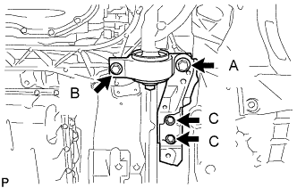
Install the front suspension lower arm and side rail plate with the 4 bolts.
- Torque:
- for bolt A
- 194 N*m { 1978 kgf*cm, 143 ft.*lbf }
- for bolt B
- 86 N*m { 877 kgf*cm, 63 ft.*lbf }
- for bolt C
- 50 N*m { 510 kgf*cm, 37 ft.*lbf }
-
Temporarily tighten the bolt, washer and nut.
-
Install the front lower ball joint with the 2 bolts.
- Torque:
- 150 N*m { 1530 kgf*cm, 111 ft.*lbf }
-
-
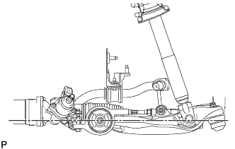
TEMPORARILY TIGHTEN FRONT SHOCK ABSORBER WITH COIL SPRING
-
Install the front shock absorber with front coil spring on the vehicle by tightening the 3 nuts on the suspension support side.
- Torque:
- 67 N*m { 683 kgf*cm, 49 ft.*lbf }
-
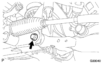
Insert the bolt from the rear of the vehicle, and install the front shock absorber lower side on the front suspension lower arm.
-
Temporarily tighten the nut while holding the bolt.
-
Tighten a new lock nut.
- Torque:
- 28 N*m { 286 kgf*cm, 21 ft.*lbf }
-
-
INSTALL ABSORBER CONTROL ACTUATOR
-
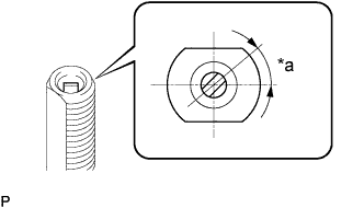
Text in Illustration *a 40° Check that the control rod of the front shock absorber is in the position shown in the illustration.
Note
If the control rod is not in the position shown in the illustration, turn the control rod to adjust the position before installing the absorber control actuator.
-
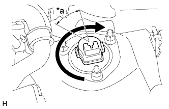
Text in Illustration *a 40° Install the absorber control actuator to the actuator support bracket.
-
Turn the actuator clockwise 40° until a click is felt.
Note
-
Before turning the actuator, make sure to check that the actuator output shaft and control rod are securely connected.
-
Do not turn the actuator more than 40°.
-
Do not drop the absorber control actuator. If it is dropped, replace it with a new one.
-
-
-
INSTALL UPPER SHOCK ABSORBER CAP
-
Connect the connector.
-
Install the upper shock absorber cap with the 3 nuts.
- Torque:
- 20 N*m { 200 kgf*cm, 14 ft.*lbf }
-
-
CONNECT FRONT STABILIZER LINK ASSEMBLY
-
Install the front stabilizer link assembly LH with the 2 nuts.
- Torque:
- 84 N*m { 857 kgf*cm, 62 ft.*lbf }
Tech Tips
If the ball joint turns together with the nut, use a 6 mm hexagon wrench to hold the stud.
-
-
CONNECT TIE ROD ASSEMBLY
-
Connect the tie rod assembly LH to the steering knuckle with the nut.
- Torque:
- 65 N*m { 663 kgf*cm, 48 ft.*lbf }
Note
If the holes for the clip are not aligned, tighten the nut up to an additional 60°.
-
Install a new clip.
-
-
CONNECT FRONT SUSPENSION UPPER ARM ASSEMBLY
-
Install the steering knuckle to the front suspension upper arm, and tighten it with the castle nut.
- Torque:
- 87 N*m { 887 kgf*cm, 64 ft.*lbf }
-
Install a new clip to the steering knuckle.
Note
Further tighten the nut up to 60° if the holes for the cotter pin are not aligned.
-
-
CONNECT SKID CONTROL SENSOR WIRE
-
Install the skid control sensor to the front shock absorber with coil spring with the bolt.
- Torque:
- 6.0 N*m { 61 kgf*cm, 53 in.*lbf }
Note
-
Do not twist the skid control sensor while installing.
-
Be careful not to deform the bracket of the front shock absorber with coil spring when installing the bolt.
-
-
STABILIZE SUSPENSION
-
Install the front wheels.
- Torque:
- 103 N*m { 1050 kgf*cm, 76 ft.*lbf }
-
Lower the vehicle and bounce it up and down several times to stabilize the front suspension.
-
Remove the front wheels.
-
Jack up the front suspension lower arm placing a wooden block in between. Apply a load to the front suspension so that the front suspension lower arm is placed in a horizontal position.
-
-
FULLY TIGHTEN FRONT SHOCK ABSORBER WITH COIL SPRING
-
Fully tighten the bolt on the lower side of the front shock absorber while holding the nut.
- Torque:
- 108 N*m { 1101 kgf*cm, 80 ft.*lbf }
-
-
FULLY TIGHTEN FRONT SUSPENSION LOWER ARM ASSEMBLY
-
Fully tighten the bolt on the front of the front suspension lower arm.
- Torque:
- 135 N*m { 1377 kgf*cm, 100 ft.*lbf }
-
Fully tighten the installation nut of the lower arm No. 2 bracket sub-assembly.
- Torque:
- 113 N*m { 1152 kgf*cm, 83 ft.*lbf }
-
-
INSTALL NO. 2 ENGINE UNDER COVER
-
Install the No. 2 engine under cover with the 4 screws and 2 grommets.
-
-
INSTALL FRONT SUSPENSION MEMBER BRACE
-
Install the front suspension member brace with the clip and 4 bolts.
- Torque:
- 52 N*m { 530 kgf*cm, 38 ft.*lbf }
-
-
INSTALL ENGINE UNDER COVER
-
Install the engine under cover with the 13 screws and 3 clips.
-
-
INSTALL FRONT WHEEL
- Torque:
- 103 N*m { 1050 kgf*cm, 76 ft.*lbf }
-
INSPECT AND ADJUST FRONT WHEEL ALIGNMENT