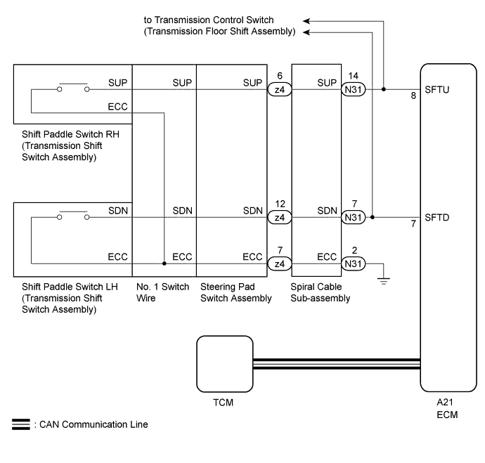
СИСТЕМА АВТОМАТИЧЕСКОЙ ТРАНСМИССИИ Shift Paddle Switch Circuit
DESCRIPTION
When the shift lever is in D, operating the "-" side shift paddle switch will cause the transmission to enter fixed range mode which restricts the highest gear. By operating the shift paddle switches "+" (UP) or "-" (DOWN), the shift range can be changed.
When the vehicle is being driven in D (fixed range mode), if the vehicle is stopped or the accelerator pedal is kept steady for a certain period of time with the transmission in the same gear, the vehicle will change back automatically to normal D position operation.
When the shift lever is in M, it is possible to make use of the highest engine speeds by holding the vehicle in a gear. Gear hold control means that gear shifts will not be performed as long as the paddle switches are not operated in either the "+" (UP) or "-" (DOWN) direction.
WIRING DIAGRAM
INSPECTION PROCEDURE
PROCEDURE
-
CHECK HARNESS AND CONNECTOR (SPIRAL CABLE - BODY GROUND)
-
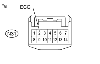
Text in Illustration *a Front view of wire harness connector
(to Spiral Cable Sub-assembly)
Disconnect the spiral cable connector Click here.
-
Measure the resistance according to the value(s) in the table below.
Standard Resistance Tester Connection Condition Specified Condition N31-2 (ECC) - Body ground Always Below 1 Ω
NG 
REPAIR OR REPLACE HARNESS OR CONNECTOR
OK 
-
-
INSPECT SPIRAL CABLE SUB-ASSEMBLY
-
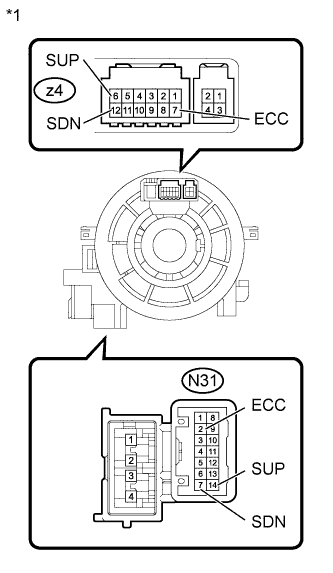
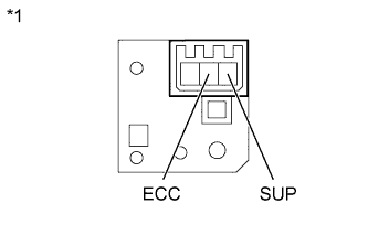
Text in Illustration *1 Spiral Cable Sub-assembly Remove the spiral cable sub-assembly Click here.
-
Measure the resistance according to the value(s) in the table below.
-
After setting the spiral cable to the center position, rotate the spiral cable 2.5 times clockwise and measure the resistance. Then rotate the spiral cable 2.5 times counterclockwise and measure the resistance.
-
After setting the spiral cable to the center position, rotate the spiral cable 2.5 times clockwise. Then while rotating the spiral cable 5 times counterclockwise, measure the resistance.
Standard Resistance Tester Connection Condition Specified Condition N31-2 (ECC) - z4-7 (ECC) Always Below 1 Ω N31-14 (SUP) - z4-6 (SUP) Always Below 1 Ω N31-7 (SDN) - z4-12 (SDN) Always Below 1 Ω N31-2 (ECC) or z4-7 (ECC) - All other terminals Always 10 kΩ or higher N31-14 (SUP) or z4-6 (SUP) - All other terminals Always 10 kΩ or higher N31-7 (SDN) or z4-12 (SDN) - All other terminals Always 10 kΩ or higher Note
As the spiral cable may break, do not rotate the spiral cable more than the specified amount.
-
NG
REPLACE SPIRAL CABLE SUB-ASSEMBLY Click here
OK
-
-
INSPECT SHIFT PADDLE SWITCH LH (TRANSMISSION SHIFT SWITCH ASSEMBLY)
-
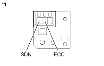
Text in Illustration *1 Shift Paddle Switch LH (Transmission Shift Switch Assembly) Remove the shift paddle switch LH Click here.
-
Measure the resistance according to the value(s) in the table below.
Standard Resistance Tester Connection Switch Condition Specified Condition SDN - ECC "-" shift paddle operated and held (down-shift) Below 2.5 Ω SDN - ECC "-" shift paddle not operated (down-shift) 1 MΩ or higher
NG
REPLACE SHIFT PADDLE SWITCH LH (TRANSMISSION SHIFT SWITCH ASSEMBLY) Click here
OK
-
-
INSPECT SHIFT PADDLE SWITCH RH (TRANSMISSION SHIFT SWITCH ASSEMBLY)
-
Text in Illustration *1 Shift Paddle Switch RH (Transmission Shift Switch Assembly) Remove the shift paddle switch RH Click here.
-
Measure the resistance according to the value(s) in the table below.
Standard Resistance Tester Connection Switch Condition Specified Condition SUP - ECC "+" shift paddle operated and held (up-shift) Below 2.5 Ω SUP - ECC "+" shift paddle not operated (up-shift) 1 MΩ or higher
NG
REPLACE SHIFT PADDLE SWITCH RH (TRANSMISSION SHIFT SWITCH ASSEMBLY) Click here
OK
-
-
INSPECT NO. 1 SWITCH WIRE
-
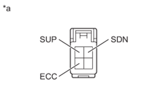
Text in Illustration *a No. 1 Switch Wire (Steering Pad Switch Side) Disconnect the No. 1 switch wire connector.
-
Measure the resistance according to the value(s) in the table below.
Standard Resistance Tester Connection Switch Condition Specified Condition SDN - ECC "-" shift paddle operated and held (down-shift) Below 2.5 Ω SUP - ECC "+" shift paddle operated and held (up-shift) Below 2.5 Ω SDN - ECC "-" shift paddle not operated (down-shift) 1 MΩ or higher SUP - ECC "+" shift paddle not operated (up-shift) 1 MΩ or higher
NG
REPLACE NO. 1 SWITCH WIRE Click here
OK
-
-
INSPECT STEERING PAD SWITCH ASSEMBLY
-
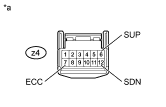
Text in Illustration *a Steering Pad Switch Assembly Connector (to Spiral Cable Sub-assembly) Disconnect the steering pad switch assembly connector Click here.
-
Measure the resistance according to the value(s) in the table below.
Standard Resistance Tester Connection Switch Condition Specified Condition z4-6 (SUP) - z4-7 (ECC) "+" shift paddle operated and held (up-shift) Below 2.5 Ω z4-12 (SDN) - z4-7 (ECC) "-" shift paddle operated and held (down-shift) Below 2.5 Ω z4-6 (SUP) - z4-7 (ECC) "+" shift paddle not operated (up-shift) 1 MΩ or higher z4-12 (SDN) - z4-7 (ECC) "-" shift paddle not operated (down-shift) 1 MΩ or higher
NG
REPLACE STEERING PAD SWITCH ASSEMBLY Click here
OK
-
-
CHECK HARNESS AND CONNECTOR (SHIFT PADDLE SWITCH - ECM)
-
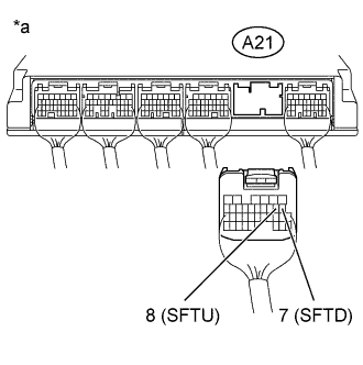
Text in Illustration *a Rear view of wire harness connector
(to ECM)
Disconnect the ECM connectors.
-
Measure the resistance according to the value(s) in the table below.
Standard Resistance Tester Connection Switch Condition Specified Condition A21-8 (SFTU) - Body ground "+" shift paddle operated and held (up-shift) Below 2.5 Ω A21-7 (SFTD) - Body ground "-" shift paddle operated and held (down-shift) Below 2.5 Ω A21-8 (SFTU) - Body ground "+" shift paddle not operated (up-shift) 1 MΩ or higher A21-7 (SFTD) - Body ground "-" shift paddle not operated (down-shift) 1 MΩ or higher
NG
REPAIR OR REPLACE HARNESS OR CONNECTOR
OK 
PROCEED TO NEXT SUSPECTED AREA SHOWN IN PROBLEM SYMPTOMS TABLE Click here
-