СИСТЕМА АВТОМАТИЧЕСКОЙ ТРАНСМИССИИ, Diagnostic DTC:P2769, P2770
| DTC Code | DTC Name |
|---|---|
| P2769 | Short in Torque Converter Clutch Solenoid Circuit (Shift Solenoid Valve SL) |
| P2770 | Open in Torque Converter Clutch Solenoid Circuit (Shift Solenoid Valve SL) |
DESCRIPTION
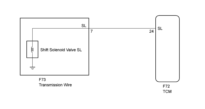
By turning the shift solenoid valve SL ON or OFF, the TCM controls the fluid pressure to the lock-up relay valve, performing lock-up control.
| DTC No. | DTC Detection Condition | Trouble Area |
|---|---|---|
| P2769 | The TCM detects a short in the shift solenoid valve SL circuit 1 time when solenoid valve SL is operated (2 trip detection logic) |
|
| P2770 | The TCM detects an open in the shift solenoid valve SL circuit 1 time when solenoid valve SL is operated (2 trip detection logic) |
|
Fail-safe function:
If the TCM detects a malfunction, it turns the shift solenoid valve SL OFF.
MONITOR DESCRIPTION
Based on the signals from the throttle position sensor, the air flow meter and the crankshaft position sensor, the TCM sends a signal to the shift solenoid valve SL to regulate the hydraulic pressure and provide smooth torque converter assembly engagement. The shift solenoid valve SL responds to commands from the TCM and controls the lock-up relay valve to perform the torque-converter lock-up function. If the TCM detects an open or short circuit in the shift solenoid valve SL circuit, it will illuminate the MIL and store a DTC.
WIRING DIAGRAM
INSPECTION PROCEDURE
Note
Perform registration and/or initialization when parts related to the automatic transmission are replaced Click here.
PROCEDURE
-
CHECK HARNESS AND CONNECTOR (SHIFT SOLENOID VALVE SL - TCM)
-
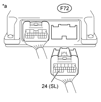
Text in Illustration *a Rear view of wire harness connector
(to TCM)
Disconnect the TCM connector.
-
Measure the resistance according to the value(s) in the table below.
Standard Resistance Tester Connection Condition Specified Condition F72-24 (SL) - Body ground Always 11 to 15 Ω
NG 
CHECK HARNESS AND CONNECTOR (TRANSMISSION WIRE - TCM) Click here
OK 
-
-
REPLACE TCM
-
Replace the TCM Click here.
NEXT 
PERFORM A/T CODE REGISTRATION Click here
-
-
CHECK HARNESS AND CONNECTOR (TRANSMISSION WIRE - TCM)
-
Disconnect the F73 transmission wire connector.
-
Disconnect the F72 TCM connector.
-
Measure the resistance according to the value(s) in the table below.
Standard Resistance Tester Connection Condition Specified Condition F73-7 (SL) - F72-24 (SL) Always Below 1 Ω F73-7 (SL) or F72-24 (SL) - Body ground Always 10 kΩ or higher
NG 
REPAIR OR REPLACE HARNESS OR CONNECTOR
OK
-
-
INSPECT SHIFT SOLENOID VALVE SL
-
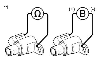
Text in Illustration *1 Shift Solenoid Valve SL Remove the shift solenoid valve SL Click here.
-
Measure the resistance according to the value(s) in the table below.
Standard Resistance Tester Connection Condition Specified Condition Shift solenoid valve SL connector - Shift solenoid valve SL Body 20°C (68°F) 11 to 15 Ω -
Connect a positive (+) battery lead to the terminal of the solenoid valve connector, and a negative (-) battery lead to the solenoid body. Then check that the valve moves and makes an operating sound.
OK Valve moves and makes an operating sound.
NG
REPLACE SHIFT SOLENOID VALVE SL Click here
OK
REPAIR OR REPLACE TRANSMISSION WIRE Click here
-