БЛОК АВТОМАТИЧЕСКОЙ ТРАНСМИССИИ ПОВТОРНАЯ СБОРКА

-
BEARING POSITION
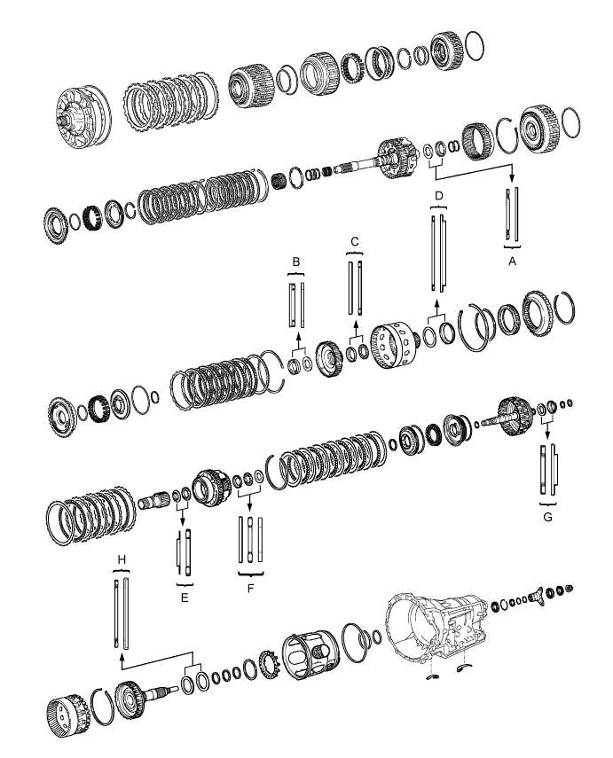
Bearing Position Position Front Race Diameter
Inside/Outside
Thrust Bearing Diameter
Inside/Outside
Rear Race Diameter
Inside/Outside
A - 36.2 mm (1.425 in.) / 58.2 mm (2.291 in.) 44.0 mm (1.732 in.) / 62.0 mm (2.441 in.) B - 34.5 mm (1.358 in.) / 49.4 mm (1.945 in.) 36.6 mm (1.441 in.) / 51.9 mm (2.043 in.) C 46.5 mm (1.831 in.) / 60.1 mm (2.366 in.) 47.0 mm (1.850 in.) / 61.9 mm (2.437 in.) - D - 71.9 mm (2.831 in.) / 85.6 mm (3.370 in.) 72.7 mm (2.858 in.) / 89.2 mm (3.512 in.) E 30.0 mm (1.181 in.) / 49.9 mm (1.965 in.) 31.0 mm (1.221 in.) / 53.1 mm (2.091 in.) - F 31.5 mm (1.240 in.) / 53.0 mm (2.087 in.) 28.7 mm (1.130 in.) / 52.3 mm (2.059 in.) 28.7 mm (1.130 in.) / 50.4 mm (1.984 in.) G - 30.5 mm (1.201 in.) / 55.7 mm (2.189 in.) 33.5 mm (1.319 in.) / 59.0 mm (2.323 in.) H - 58.9 mm (2.319 in.) / 76.7 mm (3.020 in.) 62.0 mm (2.441 in.) / 82.5 mm (3.248 in.) -
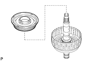
INSTALL OUTPUT SHAFT REAR RADIAL BALL BEARING
-
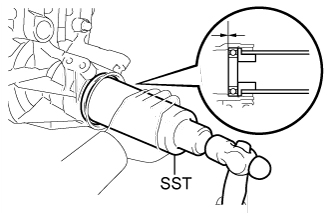
Using SST, tap in a new output shaft rear radial ball bearing to the automatic transmission case sub-assembly.
- SST
- 09316-60011 ( 09316-00011, 09316-00021 )
Tech Tips
Install the output shaft rear radial ball bearing so that there is no clearance between the output shaft rear radial ball bearing and the automatic transmission case sub-assembly.
-
Using needle-nose pliers, install the snap ring.
-
-
INSTALL AUTOMATIC TRANSMISSION REAR OIL SEAL
-
Coat the lip of a new automatic transmission rear oil seal with MP grease.
-
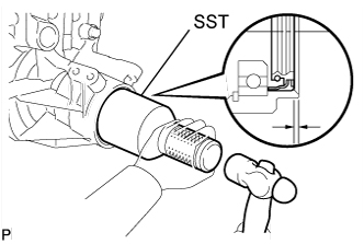
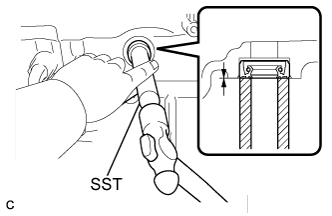
Using SST and a hammer, tap in the automatic transmission rear oil seal until it fits with the automatic transmission case sub-assembly.
- SST
- 09214-76011
Standard oil seal depth 3.3 to 3.7 mm (0.130 to 0.145 in.)
-
-
INSTALL BRAKE PLATE STOPPER SPRING
-
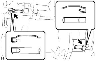
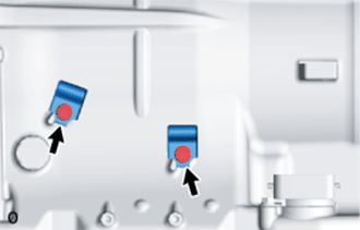
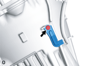
Install the 2 brake plate stopper springs.
Note
The shapes of the parts are different. Refer to the illustration when installing the parts.
-
-
INSTALL NO. 2 BRAKE PISTON
-
Coat 3 new O-rings with ATF, and install them to the No. 2 brake piston.
-
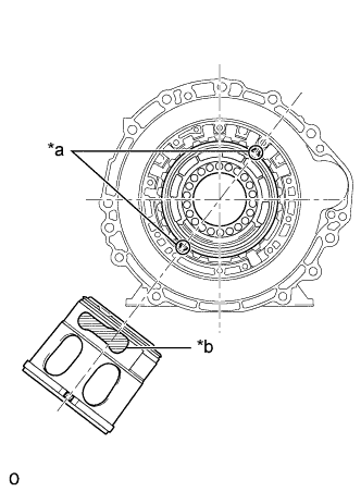
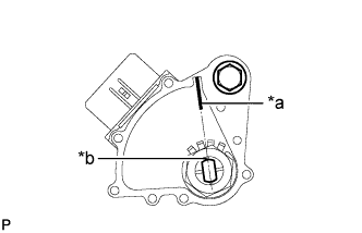
Text in Illustration *a Spline *b Parking Hole Install the No. 2 brake piston to the automatic transmission case sub-assembly.
Tech Tips
Make sure that the parking hole of the No. 2 brake piston is on the bottom side by engaging the 2 protrusions of the brake piston to the spline grooves of the transmission case. (One groove is 3 places clockwise from the top, and the other is 2 places clockwise from the bottom).
-
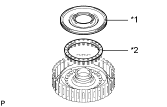
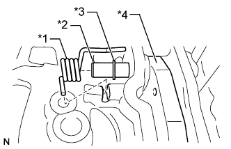
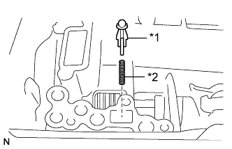
Install the No. 2 brake piston return spring sub-assembly to the automatic transmission case sub-assembly.
-
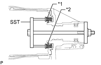
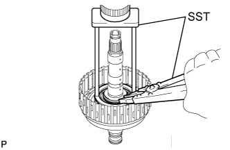
Text in Illustration *1 No. 2 Brake Piston Return Spring Sub-assembly *2 Snap Ring Set SST on the No. 2 brake piston return spring sub-assembly, tighten SST and compress the No. 2 brake piston return spring sub-assembly.
- SST
- 09380-50010 ( 09381-05010, 09381-05020 )
-
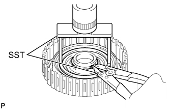
Using SST, install the snap ring.
- SST
- 09350-30020 ( 09350-07070 )
-
-
INSPECT PACK CLEARANCE OF NO. 2 BRAKE
-
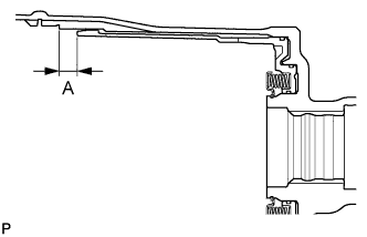
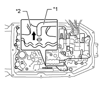
Using a vernier caliper, measure dimension A (from the tip of the No. 2 brake piston to the step in the automatic transmission case sub-assembly) in the illustration, and calculate the average.
Tech Tips
Dimension A = 14.77 to 15.37 mm (0.5815 to 0.6051 in.)
-
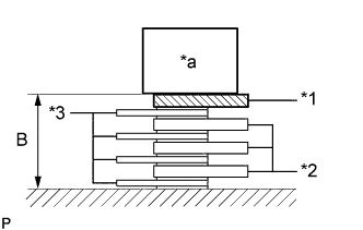
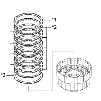
Text in Illustration *1 No. 2 Brake Flange *2 No. 2 Brake No. 2 Plate *3 No. 2 Brake Disc *a Weight Using a vernier caliper, assemble the 4 No. 2 brakes discs, 3 No. 2 brake plates and No. 2 brake flange as shown in the illustration. Then with a weight fixture of 500 g (17.64 oz) or less placed on the flange, measure dimension B, and calculate the average.
Tech Tips
-
Dimension B = 13.16 to 14.76 mm (0.5182 to 0.5811 in.)
-
Pack clearance = Dimension A - Dimension B
Pack clearance 0.52 to 0.82 mm (0.0205 to 0.0322 in.) -
-
If the pack clearance is outside the standard range, select and install a No. 2 brake flange that brings the pack clearance within the standard range.
Tech Tips
There are 9 types of No. 2 brake flanges that can be used to adjust the pack clearance. Select the one with the most appropriate thickness.
Flange thickness Part No. Mark Thickness 35678-50010 0 1.95 to 2.05 mm (0.0768 to 0.0807 in.) 35678-50020 1 2.05 to 2.15 mm (0.0808 to 0.0846 in.) 35678-50030 2 2.15 to 2.25 mm (0.0847 to 0.0885 in.) 35678-50040 3 2.25 to 2.35 mm (0.0886 to 0.0925 in.) 35678-50050 4 2.35 to 2.45 mm (0.0926 to 0.0964 in.) 35678-50060 5 2.45 to 2.55 mm (0.0965 to 0.1003 in.) 35678-50070 6 2.55 to 2.65 mm (0.1004 to 0.1043 in.) 35678-50080 7 2.65 to 2.75 mm (0.1044 to 0.1082 in.) 35678-50090 8 2.75 to 2.85 mm (0.1083 to 0.1122 in.)
-
-
INSTALL DIRECT CLUTCH PISTON
-
Coat a new O-ring with ATF, and install it to the direct clutch drum sub-assembly.
-
Coat a new O-ring with ATF, and install it to the direct clutch piston.
-
Install the direct clutch piston to the direct clutch drum sub-assembly.
-
Coat a new O-ring with ATF, and install it to the No. 2 clutch balancer.
-
Text in Illustration *1 No. 2 Clutch Balancer *2 Direct Clutch Return Spring Sub-assembly Install the direct clutch return spring sub-assembly and No. 2 clutch balancer to the direct clutch drum sub-assembly.
-
Place SST on the No. 2 clutch balancer and compress the direct clutch return spring sub-assembly with a press.
- SST
- 09387-00020
-
Using SST, install the snap ring.
- SST
- 09350-30020 ( 09350-07070 )
-
-
INSTALL NO. 2 CLUTCH DISC SET
-
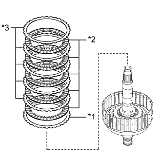
Text in Illustration *1 No. 2 Clutch Flange *2 No. 2 Clutch Disc *3 No. 2 Clutch Plate Install the 5 No. 2 clutch plates, 5 No. 2 clutch discs and the No. 2 clutch flange to the direct clutch drum sub-assembly.
Install in order *1 - *2 - *3 - *2 - *3 - *2 - *3 - *2 - *3 - *2 - *3 Note
Make sure that the No. 2 clutch discs, No. 2 clutch plates and the No. 2 clutch flange are installed in the correct order.
-
Install the snap ring to the direct clutch drum sub-assembly.
-
Temporarily remove the snap ring, install the selected flange and reinstall the snap ring.
-
-
INSPECT PACK CLEARANCE OF NO. 2 CLUTCH
-

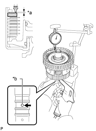
Text in Illustration *a Oil Hole *b Distance A Using a dial indicator, measure the moving distance (distance A) of the No. 2 clutch flange at both ends across the diameter while blowing compressed air (196 kPa, 2.0 kgf/cm2, 28 psi) from the oil hole as shown in the illustration, and calculate the average.
Pack clearance 0.90 to 1.20 mm (0.0355 to 0.0472 in.) -
If the pack clearance is outside the standard range, select and install a No. 2 clutch flange that brings the pack clearance within the standard range.
Tech Tips
There are 9 types of No. 2 clutch flanges that can be used to adjust the pack clearance. Select the one with the most appropriate thickness.
Flange thickness Part No. Mark Thickness 35635-50181 40 3.95 to 4.05 mm (0.1556 to 0.1594 in.) 35635-50191 41 4.05 to 4.15 mm (0.1595 to 0.1633 in.) 35635-50201 42 4.15 to 4.25 mm (0.1634 to 0.1673 in.) 35635-50211 43 4.25 to 4.35 mm (0.1674 to 0.1712 in.) 35635-50221 44 4.35 to 4.45 mm (0.1713 to 0.1751 in.) 35635-50231 45 4.45 to 4.55 mm (0.1752 to 0.1791 in.) 35635-50241 46 4.55 to 4.65 mm (0.1792 to 0.1830 in.) 35635-50251 47 4.65 to 4.75 mm (0.1831 to 0.1870 in.) 35635-50261 48 4.75 to 4.85 mm (0.1871 to 0.1909 in.)
-
-
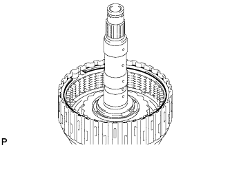
INSTALL DIRECT CLUTCH SUB-ASSEMBLY
-
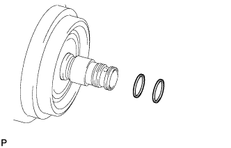
Coat 2 new oil seal rings with ATF, and install them to the direct clutch drum sub-assembly.
Note
Do not expand the ring ends excessively.
-
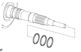
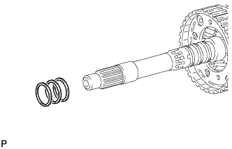
Coat 3 new oil seal rings with ATF, and install them to the output shaft sub-assembly.
Note
Do not expand the ring ends excessively.
-
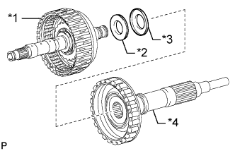
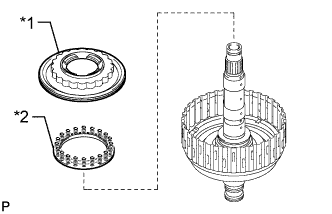
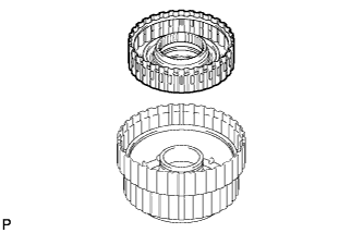
Text in Illustration *1 Direct Clutch Drum Sub-assembly *2 Thrust Needle Roller Bearing *3 Thrust Bearing Race *4 Output Shaft Sub-assembly Install the thrust needle roller bearing and thrust bearing race.
Standard Bearing and Race Diameter Item Inside Outside Thrust needle roller bearing G 30.5 mm (1.201 in.) 55.7 mm (2.189 in.) Thrust bearing race G 33.5 mm (1.319 in.) 59.0 mm (2.323 in.) Note
Use a small amount of MP grease to make the thrust needle roller bearing and thrust bearing race stay securely in place.
-
Install the direct clutch sub-assembly to the output shaft sub-assembly.
-
-
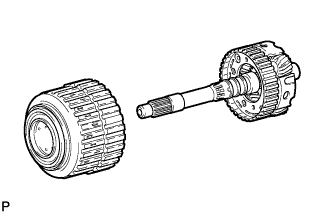
INSTALL REAR PLANETARY RING GEAR
-
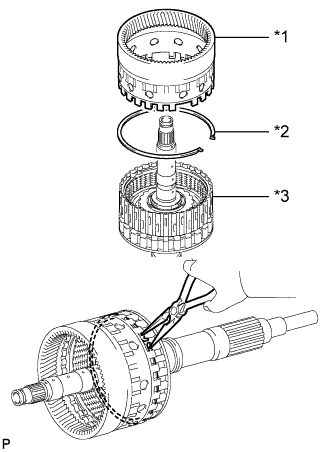
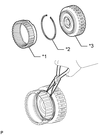
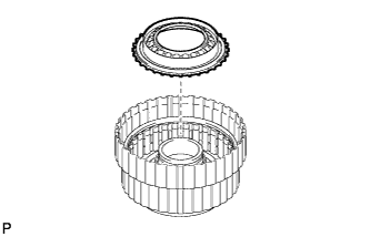
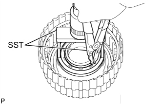
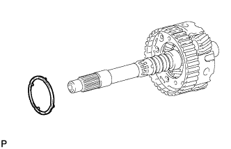
Text in Illustration *1 Rear Planetary Ring Gear *2 Snap Ring *3 Output Shaft Sub-assembly Install the snap ring to the groove of the output shaft sub-assembly.
-
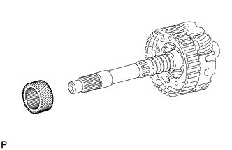
Using needle-nose pliers, attach the snap ring to install the rear planetary ring gear to the output shaft sub-assembly.
-
-
INSTALL DIRECT CLUTCH SUB-ASSEMBLY WITH REAR PLANETARY RING GEAR AND OUTPUT SHAFT SUB-ASSEMBLY
-
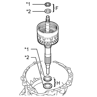
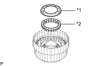
Text in Illustration *1 Thrust Needle Roller Bearing *2 Thrust Bearing Race Install the 2 thrust needle bearings, 2 thrust bearing races, direct clutch with rear planetary ring gear and output shaft to the transmission case.
Standard Bearing and Race Diameter Item Inside Outside Thrust bearing race H 62.0 mm (2.441 in.) 82.5 mm (3.248 in.) Thrust needle roller bearing H 58.9 mm (2.319 in.) 76.7 mm (3.020 in.) Thrust bearing race F
(Rear)
28.7 mm (1.130 in.) 50.4 mm (1.984 in.) Thrust needle roller bearing F 28.7 mm (1.130 in.) 52.3 mm (2.059 in.) Note
Use a small amount of MP grease to make the thrust needle roller bearing and thrust bearing race stay securely in place.
-
-
INSTALL AUTOMATIC TRANSMISSION FLANGE YOKE ASSEMBLY
-
Coat the lip of a new oil seal with MP grease.
-
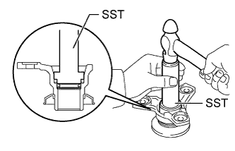
Using SST and a hammer, tap in the oil seal to the automatic transmission flange yoke assembly.
- SST
- 09517-36010
Standard depth 0 to 0.3 mm (0 to 0.0118 in.) -
Install the rear cover sleeve and 2 rear No. 1 output shaft bearing spacers.
-
Install the automatic transmission flange yoke assembly.
-
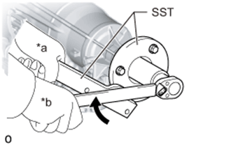
Text in Illustration *a Hold *b Turn Set SST.
- SST
- 09330-00021
- 09950-30012 ( 09955-03040 )
-
Using SST and a 30 mm deep socket wrench, temporarily install and tighten a new lock nut.
- Torque:
- 135 N*m { 1376 kgf*cm, 99 ft.*lbf }
-
-
SELECT REAR COVER SLEEVE
-
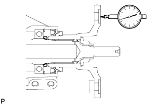
Using a dial indicator, measure the output shaft end play. Then choose from the 15 sleeve thicknesses in the table so that the measured value is within the standard value.
Standard end play 0.21 to 0.36 mm (0.0083 to 0.0141 in.) Sleeve thickness Part No. Mark Thickness 35155-50080 02 1.725 to 1.775 mm (0.0680 to 0.0698 in.) 35155-50090 03 1.775 to 1.825 mm (0.0699 to 0.0718 in.) 35155-50100 04 1.825 to 1.875 mm (0.0719 to 0.0738 in.) 35155-50110 05 1.875 to 1.925 mm (0.0739 to 0.0757 in.) 35155-50120 06 1.925 to 1.975 mm (0.0758 to 0.0777 in.) 35155-50130 07 1.975 to 2.025 mm (0.0778 to 0.0797 in.) 35155-50140 08 2.025 to 2.075 mm (0.0798 to 0.0816 in.) 35155-50150 09 2.075 to 2.125 mm (0.0817 to 0.0836 in.) 35155-50160 10 2.125 to 2.175 mm (0.0837 to 0.0856 in.) 35155-50170 11 2.175 to 2.225 mm (0.0857 to 0.0875 in.) 35155-50180 12 2.225 to 2.275 mm (0.0876 to 0.0895 in.) 35155-50190 13 2.275 to 2.325 mm (0.0896 to 0.0915 in.) 35155-50200 14 2.325 to 2.375 mm (0.0916 to 0.0935 in.) 35155-50210 15 2.375 to 2.425 mm (0.0936 to 0.0954 in.) 35155-50230 00 1.675 to 1.725 mm (0.0659 to 0.0679 in.) -
Temporarily remove the lock nut, automatic transmission flange yoke assembly, 2 rear No. 1 output shaft bearing spacers and rear cover sleeve, attach the automatic transmission flange yoke assembly.
-
Using a chisel and hammer, securely stake the lock nut.
-
-
INSTALL REAR PLANETARY GEAR ASSEMBLY
-
Text in Illustration *1 Thrust Needle Roller Bearing *2 Rear Planetary Gear Assembly *3 Thrust Bearing Race Install the thrust bearing race, rear planetary gear assembly and thrust needle roller bearing to the transmission case.
Standard Bearing and Race Diameter Item Inside Outside Thrust bearing race F
(Front)
31.5 mm (1.240 in.) 53.0 mm (2.087 in.) Thrust needle roller bearing E 31.0 mm (1.221 in.) 53.1 mm (2.091 in.) Note
-
Before installing the rear planetary gear assembly, apply ATF to the sliding surfaces of the rear planetary gear assembly bush. After the installation, check that the rear planetary gear assembly rotates smoothly.
-
Use a small amount of MP grease to make the thrust needle roller bearing and thrust bearing race stay securely in place.
-
-
-
INSTALL REAR PLANETARY SUN GEAR ASSEMBLY
-
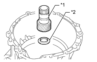
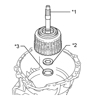
Text in Illustration *1 Rear Planetary Sun Gear Assembly *2 Thrust Bearing Race Install the thrust bearing race and rear planetary sun gear assembly to the automatic transmission case sub-assembly.
Standard Bearing Race Diameter Item Inside Outside Thrust bearing race E 30.0 mm (1.181 in.) 49.9 mm (1.965 in.) Note
-
Before installing the sun gear, apply ATF to the sliding surfaces of the sun gear bush. After the installation, check that the sun gear rotates smoothly.
-
Use a small amount of MP grease to make the thrust bearing race stay securely in place.
-
-
-
INSTALL NO. 2 BRAKE DISC SET
-
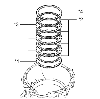
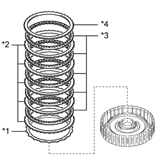
Text in Illustration *1 No. 2 Brake Flange *2 No. 2 Brake Disc *3 No. 2 Brake No. 2 Plate *4 No. 2 Brake No. 1 Plate Install the selected No. 2 brake flange, 4 No. 2 brake discs, 3 No. 2 brake No. 2 plates and No. 2 brake No. 1 plate to the automatic transmission case sub-assembly.
Install in order *1 - *2 - *3 - *2 - *3 - *2 - *3 - *2 - *4 Tech Tips
Assemble the automatic transmission case sub-assembly, No. 2 brake flange, No. 2 brake No. 2 plate and No. 2 brake No. 1 plate by aligning their grooves as shown in the illustration.
Text in Illustration *1 No. 2 Brake Flange *2 No. 2 Brake No. 1 Plate *3 No. 2 Brake No. 2 Plate - - *a Groove - - Note
Make sure that the discs, plates and the flange are installed in the correct order.
-
-
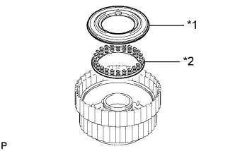
INSTALL NO. 1 ONE-WAY CLUTCH
-
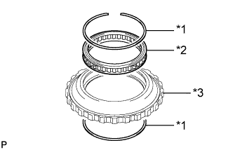
Text in Illustration *1 Snap Ring *2 No. 1 One-way Clutch *3 One-way Clutch Outer Race Install the No. 1 one-way clutch to the one-way clutch outer race with the 2 snap rings.
Note
Make sure that the No. 1 one-way clutch is oriented correctly.
-
-
INSPECT NO. 1 ONE-WAY CLUTCH
-
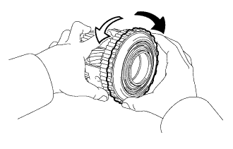
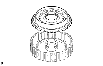
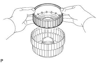
Set the one-way clutch to the rear planetary gear assembly.
Text in Illustration 
Lock 
Free -
Hold the rear planetary gear assembly and turn the one-way clutch.
-
Check that the one-way clutch turns freely counterclockwise and locks clockwise.
If there is a problem with the one-way clutch, replace it.
-
-
INSTALL ONE-WAY CLUTCH OUTER RACE WITH NO. 1 ONE-WAY CLUTCH
-
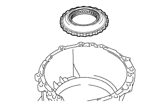
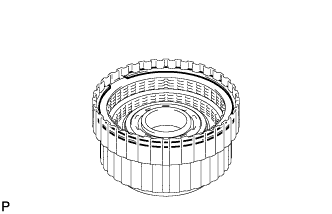
Install the one-way clutch outer race with No. 1 one-way clutch to the automatic transmission case sub-assembly.
-
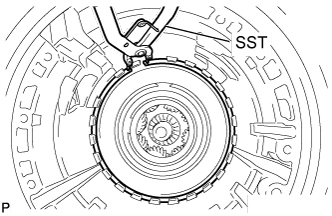
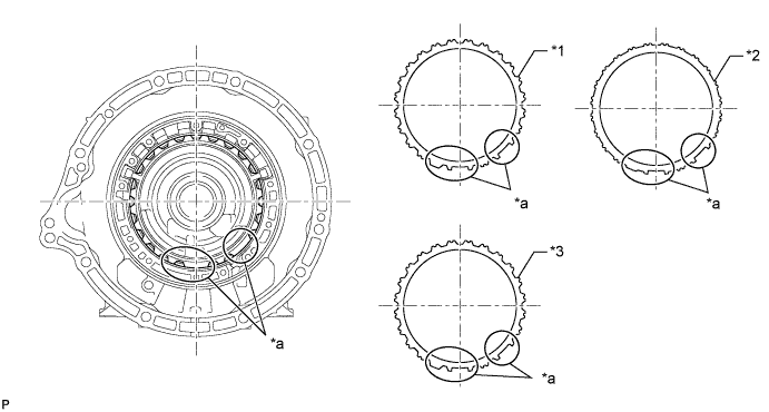
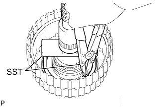
Using SST, install the snap ring to the automatic transmission case sub-assembly.
- SST
- 09350-30020 ( 09350-07060 )
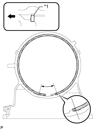
Text in Illustration *1 Snap Ring Front Side Note
-
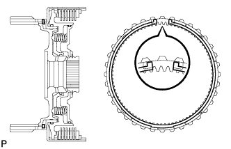
Install the snap ring so that its tapered face is facing the front side of the automatic transmission case sub-assembly.
-
Install the snap ring so that its end gap will be within the range shown in the illustration.
-
-
INSTALL SUN GEAR INPUT DRUM SUB-ASSEMBLY
-
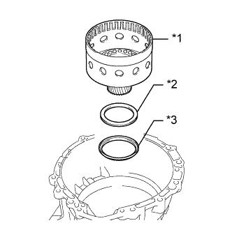
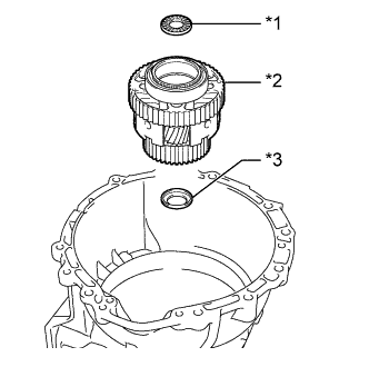
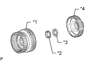
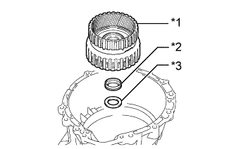
Text in Illustration *1 Sun Gear Input Drum Sub-assembly *2 Thrust Needle Roller Bearing *3 Thrust Bearing Race Install the thrust bearing race, thrust needle roller bearing and sun gear input drum.
Standard Bearing and Race Diameter Item Inside Outside Thrust bearing race D 72.7 mm (2.858 in.) 89.2 mm (3.512 in.) Thrust needle roller bearing D 71.9 mm (2.831 in.) 85.6 mm (3.370 in.) Note
-
Before installing the sun gear input drum sub-assembly, apply ATF to the sliding surfaces of the sun gear input drum sub-assembly bush. After the installation, check that the sun gear input drum sub-assembly rotates smoothly.
-
Use a small amount of MP grease to make the thrust needle roller bearing and thrust bearing race stay securely in place.
-
-
-
INSTALL FORWARD CLUTCH PISTON
-
Coat 2 new O-rings with ATF, and install them to the forward clutch piston.
-
Install the forward clutch piston to the forward clutch drum sub-assembly.
-
Coat a new O-ring with ATF, and install it to the No. 1 clutch balancer.
-
Text in Illustration *1 No. 1 Clutch Balancer *2 Forward Clutch Return Spring Sub-assembly Install the forward clutch return spring sub-assembly and No. 1 clutch balancer to the forward clutch drum sub-assembly.
-
Place SST on the No. 1 clutch balancer, and compress the No. 1 clutch balancer with a press.
- SST
- 09380-50010 ( 09381-05020 )
-
Using SST, install the snap ring.
- SST
- 09350-30020 ( 09350-07070 )
Note
-
Be sure that the end gap of the snap ring is not aligned with the spring retainer claw.
-
Stop pressing when the balancer is lowered to the place 1 to 2 mm (0.039 to 0.078 in.) from the snap ring groove to prevent spring sheet deformation.
-
Do not expand the snap ring excessively.
-
-
INSTALL FORWARD MULTIPLE CLUTCH DISC SET
-
Text in Illustration *1 Clutch Cushion Plate *2 Forward Multiple Clutch Plate *3 Forward Multiple Clutch Disc *4 Forward Clutch Flange Install the clutch cushion plate, 5 forward multiple clutch plates, 5 forward multiple clutch discs and forward clutch flange to the forward clutch drum sub-assembly.
Install in order *1 - *2 - *3 - *2 - *3 - *2 - *3 - *2 - *3 - *2 - *3 - *4 Note
-
Assemble the clutch cushion plate by facing its marked side towards the forward multiple clutch plates.
-
Make sure that the clutch cushion plate, forward multiple clutch discs, forward multiple clutch plates and the forward clutch flange are installed in the correct order.
-
-
Install the snap ring to the forward clutch drum sub-assembly.
-
-
INSPECT PACK CLEARANCE OF FORWARD MULTIPLE CLUTCH
-
Temporarily assemble the front planetary gear assembly to the forward clutch drum sub-assembly.
-
Text in Illustration *a Oil Hole *b Distance A Using a dial indicator, measure the moving distance (distance A) of the forward clutch flange at both ends across the diameter while blowing compressed air (196 kPa, 2.0 kgf/cm2, 28 psi) from the oil hole as shown in the illustration, and calculate the average.
Pack clearance 0.90 to 1.20 mm (0.0355 to 0.0472 in.) -
If the pack clearance is outside the standard range, select and install a forward clutch flange that brings the pack clearance within the standard range.
Tech Tips
There are 9 types of forward clutch flanges that can be used to adjust the pack clearance. Select the one with the most appropriate thickness.
Flange thickness Part No. Mark Thickness 35635-50090 0 4.35 to 4.45 mm (0.1713 to 0.1751 in.) 35635-50100 1 4.45 to 4.55 mm (0.1752 to 0.1791 in.) 35635-50110 2 4.55 to 4.65 mm (0.1792 to 0.1830 in.) 35635-50120 3 4.65 to 4.75 mm (0.1831 to 0.1870 in.) 35635-50130 4 4.75 to 4.85 mm (0.1871 to 0.1909 in.) 35635-50140 5 4.85 to 4.95 mm (0.1910 to 0.1948 in.) 35635-50150 6 4.95 to 5.05 mm (0.1949 to 0.1988 in.) 35635-50160 7 5.05 to 5.15 mm (0.1989 to 0.2027 in.) 35635-50170 8 5.15 to 5.25 mm (0.2028 to 0.2066 in.)
-
-
INSTALL FRONT PLANETARY RING GEAR
-
Text in Illustration *1 Front Planetary Ring Gear *2 Snap Ring *3 Forward Clutch Drum Sub-assembly Install the snap ring to the groove of the forward clutch drum sub-assembly.
-
Using needle-nose pliers, attach the snap ring to install the front planetary ring gear to the forward clutch drum sub-assembly.
Note
Check that the snap ring is securely fit into the groove by looking through the front planetary ring gear slots on both sides.
-
-
INSTALL MULTIPLE DISC CLUTCH HUB
-
Text in Illustration *1 Forward Clutch Drum Sub-assembly with Front Planetary Ring Gear *2 Thrust Needle Roller Bearing *3 Thrust Bearing Race *4 Multiple Disc Clutch Hub Install the thrust needle roller bearing, thrust bearing race and multiple disc clutch hub to the forward clutch drum sub-assembly with front planetary ring gear.
Standard Bearing and Race Diameter Item Inside Outside Thrust needle roller bearing B 34.5 mm (1.358 in.) 49.4 mm (1.945 in.) Thrust bearing race B 36.6 mm (1.441 in.) 51.9 mm (2.043 in.) Note
Use a small amount of MP grease to make the thrust needle roller bearing and thrust bearing race stay securely in place.
-
-
INSTALL FORWARD CLUTCH ASSEMBLY WITH FRONT PLANETARY RING GEAR AND MULTIPLE DISC CLUTCH HUB
-
Text in Illustration *1 Forward Clutch Drum Sub-assembly with Front Planetary Ring Gear and Multiple Disc Clutch Hub *2 Thrust Bearing Race *3 Thrust Needle Roller Bearing Install the thrust bearing race, thrust needle roller bearing and forward clutch assembly with front planetary ring gear and multiple disc clutch hub to the transmission case.
Standard Bearing and Race Diameter Item Inside Outside Thrust needle roller bearing C 47.0 mm (1.850 in.) 61.9 mm (2.437 in.) Thrust bearing race C 46.5 mm (1.831 in.) 60.1 mm (2.366 in.) Note
-
Before installing the forward multiple disc clutch assembly, apply ATF to the sliding surfaces of the forward multiple disc clutch assembly bush. After the installation, check that the forward multiple disc clutch assembly rotates smoothly.
-
Use a small amount of MP grease to make the thrust needle roller bearing and thrust needle roller bearing race stay securely in place.
-
-
-
INSTALL OVERDRIVE DIRECT CLUTCH PISTON SUB-ASSEMBLY
-
Coat a new O-ring with ATF, and install it to the overdrive direct clutch drum sub-assembly.
-
Coat a new O-ring with ATF, and install it to the overdrive direct clutch piston sub-assembly.
-
Install the overdrive direct clutch piston sub-assembly to the overdrive direct clutch drum sub-assembly.
-
Coat a new O-ring with ATF, and install it to the No. 3 clutch balancer.
-
Text in Illustration *1 No. 3 Clutch Balancer *2 Overdrive Clutch Return Spring Sub-assembly Install the overdrive clutch return spring and No. 3 clutch balancer to the overdrive direct clutch piston.
-
Place SST on the No. 3 clutch balancer, and compress the No. 3 clutch balancer with a press.
- SST
- 09380-50010 ( 09381-05020 )
-
Using SST, install the snap ring.
- SST
- 09350-30020 ( 09350-07070 )
Note
-
Be sure that the end gap of the snap ring is not aligned with the spring retainer claw.
-
Stop pressing when the balancer is lowered to the place 1 to 2 mm (0.040 to 0.078 in.) from the snap ring groove to prevent spring sheet deformation.
-
Do not expand the snap ring excessively.
-
-
INSTALL REVERSE CLUTCH DRUM SUB-ASSEMBLY
-
Coat 3 new O-rings with ATF, and install them to the reverse clutch drum sub-assembly.
-
Install the reverse clutch drum sub-assembly to the overdrive direct clutch drum sub-assembly.
-
-
INSTALL REVERSE CLUTCH PISTON
-
Coat a new O-ring with ATF, and install it to the reverse clutch piston.
-
Install the reverse clutch piston to the overdrive direct clutch drum sub-assembly.
-
Text in Illustration *1 Reverse Clutch Balancer *2 Reverse Clutch Return Spring Sub-assembly Install the reverse clutch return spring sub-assembly and reverse clutch balancer.
-
Place SST on the reverse clutch balancer, and compress the clutch balancer with a press.
- SST
- 09380-50010 ( 09381-05020 )
-
Using SST, install the snap ring.
- SST
- 09350-30020 ( 09350-07070 )
Note
-
Be sure that the end gap of the snap ring is not aligned with the spring retainer claw.
-
Stop pressing when the balancer is lowered to the place 1 to 2 mm (0.040 to 0.078 in.) from the snap ring groove to prevent spring sheet deformation.
-
Do not expand the snap ring excessively.
-
-
INSTALL REVERSE CLUTCH DISC SET
-
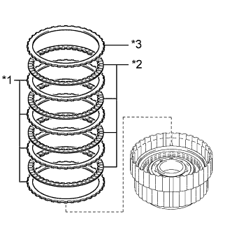
Text in Illustration *1 Reverse Clutch Flange *2 Reverse Clutch Disc *3 Reverse Clutch Plate Install the 5 reverse clutch plates, 5 reverse clutch discs and reverse clutch flange to the reverse clutch drum sub-assembly.
Install in order *1 - *2 - *1 - *2 - *1 - *2 - *1 - *2 - *1 - *2 - *3 Note
Make sure that the reverse clutch discs, reverse clutch plates and the reverse clutch flange are installed in the correct order.
-
Install the snap ring to the reverse clutch drum sub-assembly.
-
-
INSPECT PACK CLEARANCE OF REVERSE CLUTCH
-
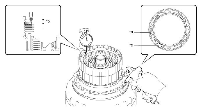
Using a dial indicator, measure the moving distance (distance A) of the reverse clutch flange at both ends across the diameter while blowing compressed air (196 kPa, 2.0 kgf/cm2, 28 psi) from the oil hole as shown in the illustration, and calculate the average.
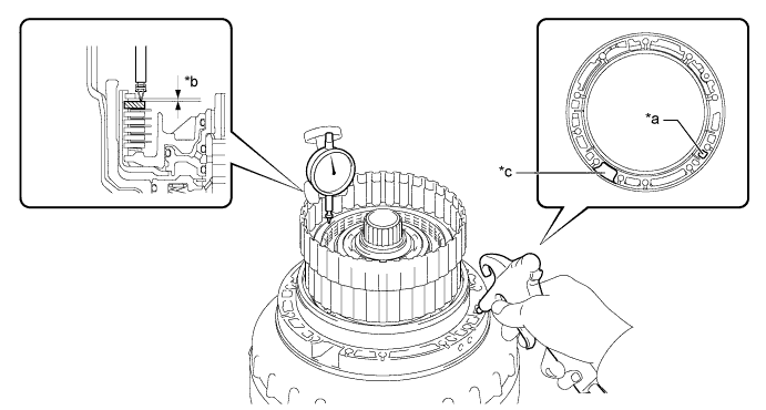
Text in Illustration *a Oil Hole *b Distance A *c Speed Sensor Hole - - Pack clearance 0.5 to 0.8 mm (0.0197 to 0.0314 in.) -
If the pack clearance is outside the standard range, select and install a reverse clutch flange that brings the pack clearance within the standard range.
Tech Tips
There are 9 types of reverse clutch flanges that can be used to adjust the pack clearance. Select the one with the most appropriate thickness.
Flange thickness Part No. Mark Thickness 35649-50080 0 2.95 to 3.05 mm (0.1162 to 0.1200 in.) 35649-50090 1 3.05 to 3.15 mm (0.1201 to 0.1240 in.) 35649-50100 2 3.15 to 3.25 mm (0.1241 to 0.1279 in.) 35649-50110 3 3.25 to 3.35 mm (0.1280 to 0.1318 in.) 35649-50120 4 3.35 to 3.45 mm (0.1319 to 0.1358 in.) 35649-50130 5 3.45 to 3.55 mm (0.1359 to 0.1397 in.) 35649-50140 6 3.55 to 3.65 mm (0.1398 to 0.1437 in.) 35649-50150 7 3.65 to 3.75 mm (0.1438 to 0.1476 in.) 35649-50160 8 3.75 to 3.85 mm (0.1477 to 0.1516 in.)
-
-
INSTALL NO. 3 CLUTCH DISC SET
-
Text in Illustration *1 No. 3 Clutch Plate *2 No. 3 Clutch Disc *3 No. 3 Clutch Flange Install the 4 No. 3 clutch plates, 4 No. 3 clutch discs and No. 3 clutch flange to the overdrive direct clutch drum sub-assembly.
Install in order *1 - *2 - *1 - *2 - *1 - *2 - *1 - *2 - *3 Note
Make sure that the No. 3 clutch discs, No. 3 clutch plates and the No. 3 clutch flange are installed in the correct order.
-
Install the snap ring to the overdrive direct clutch drum sub-assembly.
-
-
INSPECT PACK CLEARANCE OF NO. 3 CLUTCH
-
Using a dial indicator, measure the moving distance (distance A) of the No. 3 clutch flange at both ends across the diameter while blowing compressed air (196 kPa, 2.0 kgf/cm2, 28 psi) from the oil hole as shown in the illustration, and calculate the average.
Text in Illustration *a Oil Hole *b Distance A *c Speed Sensor Hole - - Pack clearance 0.4 to 0.7 mm (0.0158 to 0.0275 in.) -
If the pack clearance is outside the standard range, select and install a No. 3 clutch flange that brings the pack clearance within the standard range.
Tech Tips
There are 7 types of No. 3 clutch flanges that can be used to adjust the pack clearance. Select the one with the most appropriate thickness.
Flange thickness Part No. Mark Thickness 34615-50060 0 3.95 to 4.05 mm (0.1556 to 0.1594 in.) 34615-50070 1 4.05 to 4.15 mm (0.1595 to 0.1633 in.) 34615-50080 2 4.15 to 4.25 mm (0.1634 to 0.1673 in.) 34615-50090 3 4.25 to 4.35 mm (0.1674 to 0.1712 in.) 34615-50100 4 4.35 to 4.45 mm (0.1713 to 0.1751 in.) 34615-50110 5 4.45 to 4.55 mm (0.1752 to 0.1791 in.) 34615-50120 6 4.55 to 4.65 mm (0.1792 to 0.1830 in.)
-
-
INSTALL FRONT PLANETARY GEAR ASSEMBLY
-
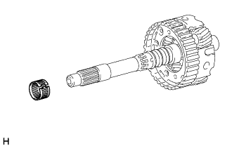
Install the front planetary gear thrust needle roller bearing to the front planetary gear assembly.
Note
Do not expand the front planetary gear thrust needle roller bearing excessively.
-
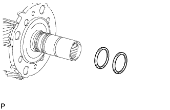
Coat 2 new oil seal rings with ATF, and install them to the front planetary gear assembly.
Note
Do not expand the ring ends excessively.
-
Coat 3 new oil seal rings with ATF, and install them to the front planetary gear assembly.
Note
Do not expand the ring ends excessively.
-
Install the planetary carrier thrust washer to the front planetary gear assembly.
Note
Use a small amount of MP grease to make the planetary carrier thrust washer stay securely in place.
-
Install the planetary sun gear to the front planetary gear assembly.
-
Assemble the front planetary gear assembly together with the planetary sun gear to the overdrive direct clutch drum sub-assembly.
-
-
INSPECT PACK CLEARANCE OF NO. 1 BRAKE
-
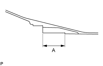
Using a vernier caliper, measure dimension A (from the step of the oil pump installation surface of the automatic transmission case sub-assembly to the step of the No. 1 brake flange installation surface) in the illustration, and calculate the average.
Tech Tips
Dimension A = 59.77 to 60.03 mm (2.3532 to 2.3633 in.)
-
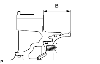
Using a vernier caliper, measure dimension B (from the flange face of the oil pump assembly to the tip of the No. 1 brake piston) in the illustration, and calculate the average.
Tech Tips
Dimension B = 34.636 to 34.964 mm (1.3637 to 1.3765 in.)
-
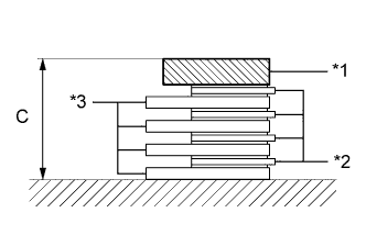
Text in Illustration *1 No. 1 Brake Flange *2 No. 1 Brake Disc *3 No. 1 Brake Plate Using a vernier caliper, assemble the 4 No. 1 brake plates, 4 No. 1 brake discs, and No. 1 brake flange, and measure dimension C in the illustration, and calculate the average.
Tech Tips
-
Dimension C = 19.41 to 21.11 mm (0.7642 to 0.8311 in.)
-
Pack clearance = Dimension A - Dimension B - Dimension C
Pack clearance 0.75 to 1.05 mm (0.0296 to 0.0413 in.) -
-
If the pack clearance is outside the standard range, select and install a No. 1 brake flange that brings the pack clearance within the standard range.
Tech Tips
There are 9 types of No. 1 brake flanges that can be used to adjust the pack clearance. Select the one with the most appropriate thickness.
Flange thickness Part No. Mark Thickness 35676-50070 0 4.45 to 4.55 mm (0.1752 to 0.1791 in.) 35676-50080 1 4.55 to 4.65 mm (0.1792 to 0.1830 in.) 35676-50090 2 4.65 to 4.75 mm (0.1831 to 0.1870 in.) 35676-50100 3 4.75 to 4.85 mm (0.1871 to 0.1909 in.) 35676-50110 4 4.85 to 4.95 mm (0.1910 to 0.1948 in.) 35676-50120 5 4.95 to 5.05 mm (0.1949 to 0.1988 in.) 35676-50130 6 5.05 to 5.15 mm (0.1989 to 0.2027 in.) 35676-50140 7 5.15 to 5.25 mm (0.2028 to 0.2066 in.) 35676-50150 8 5.25 to 5.35 mm (0.2067 to 0.2106 in.)
-
-
INSTALL OVERDRIVE DIRECT CLUTCH DRUM SUB-ASSEMBLY WITH FRONT PLANETARY GEAR ASSEMBLY
-
Text in Illustration *1 Overdrive Direct Clutch Drum Sub-assembly and Front Planetary Gear Assembly *2 Thrust Needle Roller Bearing *3 Thrust Bearing Race Install the thrust bearing race, thrust needle roller bearing, and overdrive direct clutch drum sub-assembly with front planetary gear assembly to the automatic transmission case sub-assembly.
Standard Bearing and Race Diameter Item Inside Outside Thrust needle roller bearing A 44.0 mm (1.732 in.) 62.0 mm (2.441 in.) Thrust bearing race A 36.2 mm (1.425 in.) 58.2 mm (2.291 in.) Note
-
Before installing the overdrive direct clutch drum sub-assembly, apply ATF to the sliding surfaces of the overdrive direct clutch drum sub-assembly. After the installation, check that the overdrive direct clutch drum sub-assembly rotates smoothly.
-
Use a small amount of MP grease to make the thrust bearing and thrust bearing race stay securely in place.
-
-
-
INSTALL NO. 1 BRAKE DISC SET
-
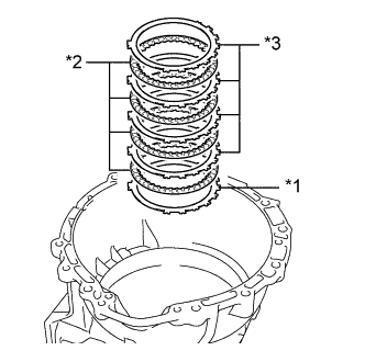
Text in Illustration *1 No. 1 Brake Flange *2 No. 1 Brake Disc *3 No. 1 Brake Plate Install the selected No. 1 brake flange, 4 No. 1 brake discs and 4 No. 1 brake plates to the automatic transmission case sub-assembly.
Install in order *1 - *2 - *3 - *2 - *3 - *2 - *3 - *2 - *3 Note
Make sure that the No. 1 brake discs, No. 1 brake plates and the No. 1 brake flange are installed in the correct order.
-
-
INSTALL OIL PUMP ASSEMBLY
-
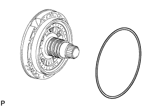
Coat a new O-ring with ATF, and install it to the oil pump assembly.
-
Clean and degrease the threads of the 11 bolts and the contact surfaces of the automatic transmission case sub-assembly and the oil pump assembly with non-residue solvent.
Note
During installation, do not allow oil to contact the bolts or the surface of the oil pump body.
-
Place the oil pump assembly through the input shaft, and align the bolt holes of the oil pump assembly with the automatic transmission case sub-assembly.
-
Hold the input shaft, and lightly press the oil pump assembly to slide the oil seal rings into the front planetary gear assembly.
Note
Be careful not to damage the O-ring and oil seal rings.
-
Apply seal packing to the flanges of the 11 bolts.
Seal packing Toyota Genuine Seal Packing 1281, Three Bond 1281 or equivalent Note
Do not allow seal packing to contact the threads of the bolts.
-
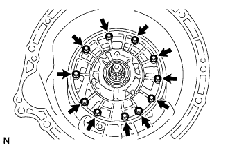
Install the 11 bolts.
- Torque:
- 21 N*m { 214 kgf*cm, 15 ft.*lbf }
-
-
INSPECT INDIVIDUAL PISTON OPERATION
-
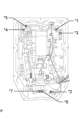
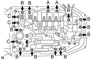
Text in Illustration *1 Forward Multiple Clutch
B
*2 No. 2 Clutch *3 No. 3 Clutch *4 Reverse Clutch *5 No. 1 Brake *6 No. 2 Brake (IN) *7 No. 2 Brake (OUT) Check the operating sound while applying compressed air into the oil holes indicated in the illustration.
-
-
INSTALL MANUAL VALVE LEVER SHAFT OIL SEAL
-
Using SST and a hammer, tap in a new manual valve lever shaft oil seal.
- SST
- 09350-30020 ( 09350-07110 )
Standard depth -0.3 to 0.3 mm (-0.0118 to 0.0118 in.) -
Coat the lip of the manual valve lever shaft oil seal with MP grease.
-
-
INSTALL MANUAL VALVE LEVER SUB-ASSEMBLY
-
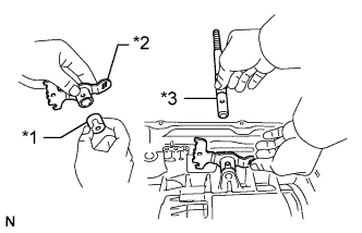
Text in Illustration *1 Spacer *2 Manual Valve Lever Sub-assembly *3 Manual Valve Lever Shaft Install a new spacer to the manual valve lever sub-assembly.
-
Install the manual valve lever shaft to the automatic transmission case sub-assembly through the manual valve lever sub-assembly.
-
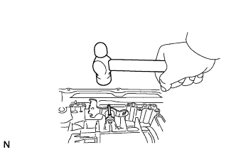
Using a hammer, tap in a new spring pin.
-
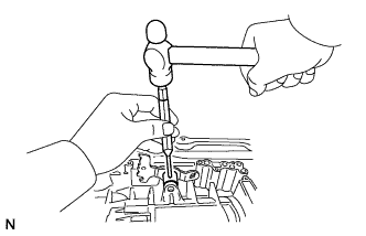
Align the manual valve lever sub-assembly indentation with the spacer hole, and stake them together with a punch.
-
Make sure that the shaft rotates smoothly.
-
-
INSTALL PARKING LOCK PAWL SHAFT
-
Text in Illustration *1 Spring *2 Parking Lock Pawl Shaft *3 E-ring *4 Parking Lock Pawl Install the E-ring to the parking lock pawl shaft.
-
Install the parking lock pawl, parking lock pawl shaft and spring.
-
-
INSTALL PARKING LOCK ROD SUB-ASSEMBLY
-
Connect the parking lock rod sub-assembly to the manual valve lever sub-assembly.
-
-
INSTALL PARKING LOCK PAWL BRACKET
-
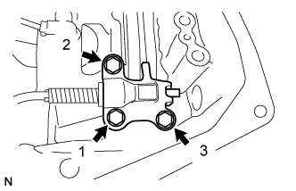
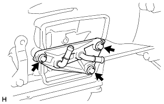
Place the parking lock pawl bracket onto the automatic transmission case sub-assembly. Loosely install the 3 bolts, and then tighten them in the order shown in the illustration.
- Torque:
- 18 N*m { 184 kgf*cm, 13 ft.*lbf }
-
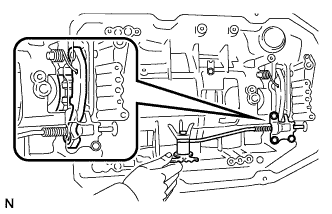
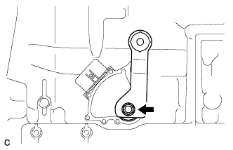
Shift the manual valve lever to the P position, and confirm that the output shaft is correctly locked up by the parking lock pawl.
-
-
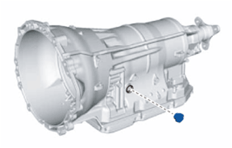
INSTALL AUTOMATIC TRANSMISSION CASE PLUG
-

Coat a new O-ring with ATF, and install it to the automatic transmission case plug.
-
Install the automatic transmission case plug to the automatic transmission case sub-assembly.
- Torque:
- 80 N*m { 816 kgf*cm, 59 ft.*lbf }
-
-
INSTALL TRANSMISSION REVOLUTION SENSOR
-
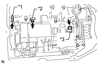
Text in Illustration *1 Transmission Revolution Sensor NT *2 Transmission Revolution Sensor NC3 *3 Transmission Revolution Sensor SP2 Coat a new O-ring with ATF and install it to the transmission revolution sensor NT.
-
Using a T30 ''TORX'' socket wrench, install the transmission revolution sensor NT with the bolt.
- Torque:
- 6.8 N*m { 69 kgf*cm, 60 in.*lbf }
-
Install the transmission revolution sensor SP2 and NC3 with the 2 bolts.
- Torque:
- 5.4 N*m { 55 kgf*cm, 48 in.*lbf }
-
-
INSTALL TRANSMISSION WIRE
-
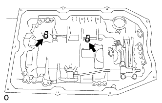
Install the 2 valve body wire harness clamps to the automatic transmission case sub-assembly with the 2 bolts.
- Torque:
- 5.4 N*m { 55 kgf*cm, 48 in.*lbf }
-
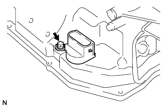
Coat a new O-ring with ATF and install it to the transmission wire connector.
Note
Ensure that the O-ring is not twisted.
-
Install the transmission wire.
-
Install the bolt.
- Torque:
- 5.4 N*m { 55 kgf*cm, 48 in.*lbf }
-
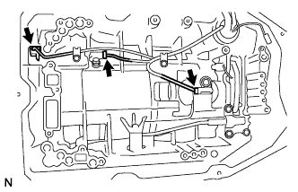
Connect the 3 connectors to the transmission revolution sensor.
-
-
INSTALL CHECK BALL BODY
-
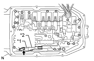
Text in Illustration *1 Check Ball Body *2 Spring Install the spring and check ball body.
-
-
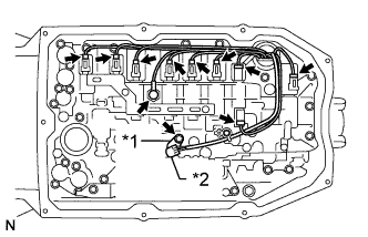
INSTALL TRANSMISSION VALVE BODY ASSEMBLY
-
Text in Illustration *1 Manual Valve Connecting Rod *2 Manual Valve Lever Sub-assembly Align the groove of the manual valve lever sub-assembly with the manual valve connecting rod.
-
Install the transmission valve body assembly with the 17 bolts.
- Torque:
- 11 N*m { 112 kgf*cm, 8 ft.*lbf }
Tech Tips
Each bolt length is indicated below.
Bolt length Bolt A 21 mm (0.827 in.) Bolt B 31 mm (1.22 in.) Bolt C 64 mm (2.52 in.) -
Text in Illustration *1 Detent Spring Cover *2 Detent Spring Install the detent spring and detent spring cover with the bolt.
- Torque:
- 10 N*m { 102 kgf*cm, 7 ft.*lbf }
Note
Make sure to install the detent spring so that its roller is perpendicularly aligned to the center of the manual valve lever.
-
Text in Illustration *1 Lock Plate *2 ATF Temperature Sensor Connect the 9 connectors to the solenoid valves.
-
Connect the oil pressure switch connector.
-
Coat a new O-ring with ATF and install it to the ATF temperature sensor.
-
Install the ATF temperature sensor and lock plate with the bolt.
- Torque:
- 10 N*m { 102 kgf*cm, 7 ft.*lbf }
-
-
INSTALL VALVE BODY OIL STRAINER ASSEMBLY
-
Coat a new O-ring with ATF and install it to the valve body oil strainer assembly.
Note
Ensure that the O-ring is not twisted or pinched.
-
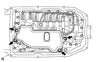
Install the valve body oil strainer assembly to the transmission valve body assembly with the 4 bolts.
- Torque:
- 10 N*m { 102 kgf*cm, 7 ft.*lbf }
-
-
INSTALL AUTOMATIC TRANSMISSION OIL PAN SUB-ASSEMBLY
-
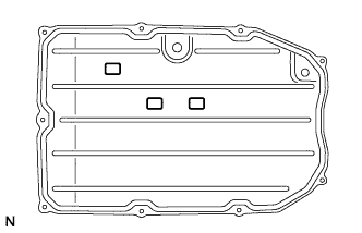
Install the 3 transmission oil cleaner magnets to the automatic transmission oil pan sub-assembly.
-
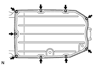
Install a new automatic transmission oil pan gasket and the automatic transmission oil pan sub-assembly to the automatic transmission case sub-assembly with the 9 bolts.
- Torque:
- 7.4 N*m { 75 kgf*cm, 65 in.*lbf }
Note
-
Make sure that there is no oil or foreign matter on the gasket seal surface and automatic transmission oil pan sub-assembly contact surface.
-
Install the gasket so that there is no slack in the gasket, and that the entire circumference of the seal surface is level.
-
Make sure that the 9 gasket drop prevention protrusions are set on the automatic transmission oil pan sub-assembly.
-
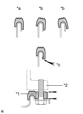
When tightening the automatic transmission oil pan sub-assembly, make sure that the gasket is not pinched between the sleeve of the gasket tightening area and the seal surface of the transmission.
Text in Illustration *1 Sleeve *2 Automatic Transmission Case Sub-assembly *a Correct *b Incorrect *c Protrusion
-
-
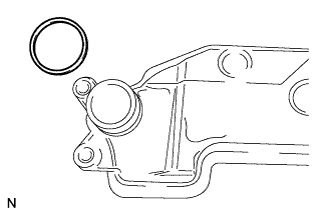
INSTALL REFILL PLUG
-
Coat a new O-ring with ATF, and install it to the refill plug.
-
Install the refill plug.
- Torque:
- 39 N*m { 400 kgf*cm, 29 ft.*lbf }
-
-
INSTALL TRANSMISSION BREATHER HOSE SUB-ASSEMBLY
-
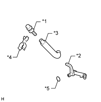
Text in Illustration *1 No. 1 Breather Plug *2 No. 2 Breather Plug *3 Breather Plug Hose *4 Clamp *5 O-ring Coat a new O-ring with ATF, and install it to the No. 2 breather plug.
Note
Ensure that the O-ring is not twisted.
-
Install the No. 1 breather plug and No. 2 breather plug to the breather plug hose.
-
Install the clamp to the No. 1 breather plug.
-
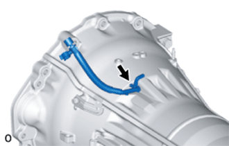
Install the transmission breather hose sub-assembly to the automatic transmission case sub-assembly.
-
-
INSTALL TRANSMISSION OIL COOLER (w/ ATF Warmer)
-
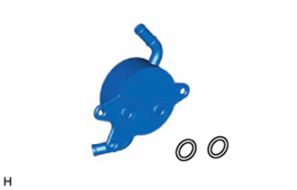
Coat 2 new O-rings with ATF, and install them to the transmission oil cooler.
-
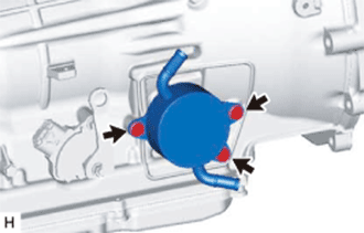
Install the transmission oil cooler to the automatic transmission case sub-assembly with the 3 bolts.
- Torque:
- 21 N*m { 214 kgf*cm, 15 ft.*lbf }
-
-
INSTALL OIL COOLER UNION SUB-ASSEMBLY (w/o ATF Warmer)
-
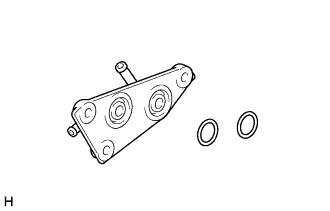
Coat 2 new O-rings with ATF, and install them to the oil cooler union sub-assembly.
-
Install the oil cooler union sub-assembly to the automatic transmission case sub-assembly with the 3 bolts.
- Torque:
- 21 N*m { 214 kgf*cm, 15 ft.*lbf }
-
-
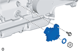
INSTALL PARK/NEUTRAL POSITION SWITCH ASSEMBLY
Note
Make sure that the manual valve lever shaft has not been rotated prior to installing the park/neutral position switch assembly as the detent spring may become detached from the manual valve lever shaft.
-
Clean the bolt and the bolt hole.
-
Apply adhesive to 2 or 3 threads on the end of the bolt.
Adhesive Toyota Genuine Adhesive 1344, Three Bond 1344 or equivalent Note
Install the bolt within 3 minutes of applying adhesive.
-
Temporarily install the park/neutral position switch assembly to the automatic transmission assembly with the bolt.
Tech Tips
Tighten the bolt to the specified torque when adjusting the park/neutral position switch assembly.
-
Install the lock washer and the lock nut to the park/neutral position switch assembly.
- Torque:
- 6.9 N*m { 70 kgf*cm, 61 in.*lbf }
-
Temporarily install the transmission control shaft lever RH to the park/neutral position switch assembly with the spring washer and nut.
Tech Tips
Tighten the nut to the specified torque when adjusting the park/neutral position switch assembly.
-
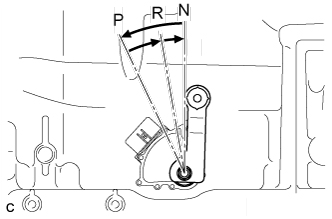
Turn the transmission control shaft lever RH counterclockwise until it stops, then turn it clockwise 2 notches.
-
Remove the nut, spring washer and transmission control shaft lever RH from the park/neutral position switch assembly.
-
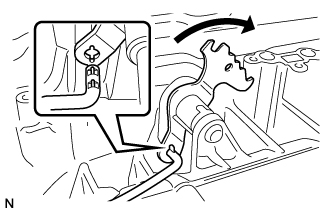
Text in Illustration *a Neutral Basic Line *b Groove Align the neutral basic line with the groove as shown in the illustration.
-
Hold the park/neutral position switch assembly in that position and tighten the bolt.
- Torque:
- 13 N*m { 130 kgf*cm, 9 ft.*lbf }
-
Using a screwdriver, stake the lock nut with the stopper plate.
-
-
INSTALL TRANSMISSION CONTROL SHAFT LEVER RH
-
Install the transmission control shaft lever RH to the park/neutral position switch assembly with the spring washer and nut.
- Torque:
- 16 N*m { 160 kgf*cm, 12 ft.*lbf }
-
-
INSTALL HARNESS BRACKET
-
Install the 2 wire harness clamp brackets to the automatic transmission case sub-assembly with the 2 bolts.
- Torque:
- 10 N*m { 102 kgf*cm, 7 ft.*lbf }
-
Install the wire harness clamp bracket to the automatic transmission case sub-assembly with the bolt.
- Torque:
- 10 N*m { 102 kgf*cm, 7 ft.*lbf }
-