БЛОК АВТОМАТИЧЕСКОЙ ТРАНСМИССИИ РАЗБОРКА

-
FIX AUTOMATIC TRANSMISSION ASSEMBLY
-
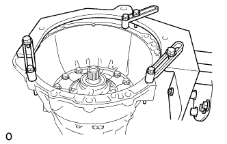
Install the automatic transmission assembly to an overhaul attachment.
-
-
REMOVE WIRE HARNESS CLAMP BRACKET
-
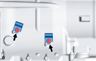
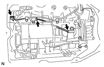
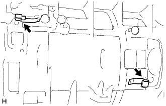
Remove the 2 bolts and 2 wire harness clamp brackets from the automatic transmission case sub-assembly.
-
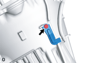
Remove the bolt and wire harness clamp bracket from the automatic transmission case sub-assembly.
-
-
REMOVE TRANSMISSION CONTROL SHAFT LEVER RH
-
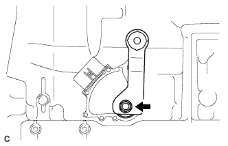
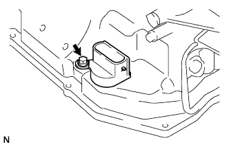
Remove the nut, spring washer and transmission control shaft lever RH from the manual valve lever shaft.
-
-
REMOVE PARK/NEUTRAL POSITION SWITCH ASSEMBLY
-
Using a screwdriver, bend the tabs of the lock washer.
-
Remove the nut and lock washer.
-
Remove the bolt and park/neutral position switch assembly.
-
-
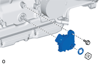
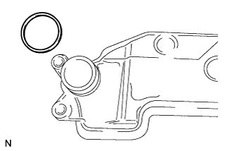
REMOVE TRANSMISSION OIL COOLER (w/ ATF Warmer)
-
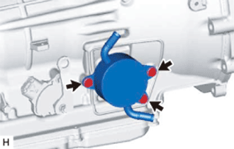
Remove the 3 bolts and transmission oil cooler from the automatic transmission case sub-assembly.
-
Remove the 2 O-rings from the transmission oil cooler.
-
-
REMOVE OIL COOLER UNION SUB-ASSEMBLY (w/o ATF Warmer)
-
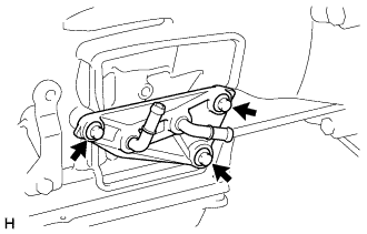
Remove the 3 bolts and oil cooler union sub-assembly from the automatic transmission case sub-assembly.
-
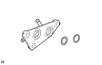
Remove the 2 O-rings from the oil cooler union sub-assembly.
-
-
REMOVE TRANSMISSION BREATHER HOSE SUB-ASSEMBLY
-
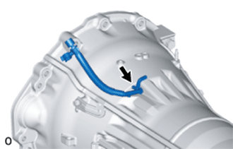
Remove the transmission breather hose sub-assembly from the automatic transmission case sub-assembly.
-
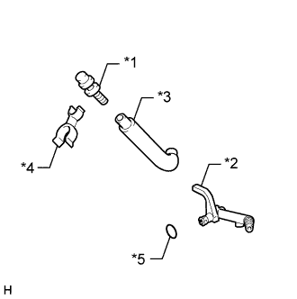
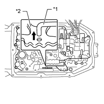
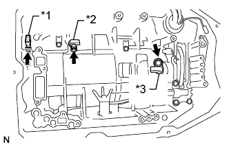
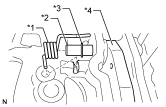
Text in Illustration *1 No. 1 Breather Plug *2 No. 2 Breather Plug *3 Breather Plug Hose *4 Clamp *5 O-ring Remove the clamp from the No. 1 breather plug.
-
Remove the No. 1 breather plug and No. 2 breather plug from the breather plug hose.
-
Remove the O-ring from the No. 2 breather plug.
-
-
REMOVE REFILL PLUG
-
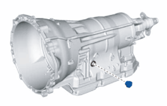
Remove the refill plug from the automatic transmission case sub-assembly.
-
Remove the O-ring from the refill plug.
-
-
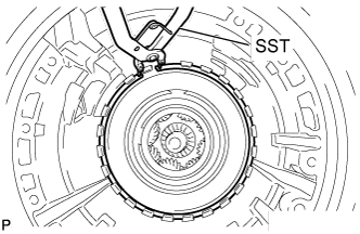
REMOVE AUTOMATIC TRANSMISSION FLANGE YOKE ASSEMBLY
-
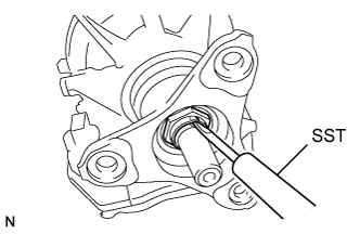
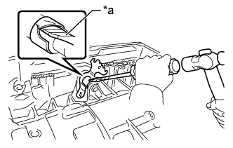
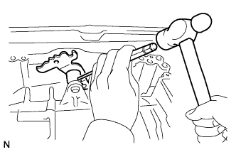
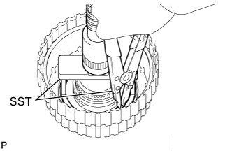
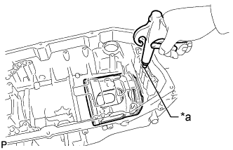
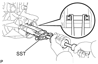
Using SST and a hammer, loosen the staked part of the lock nut.
- SST
- 09930-00010
Note
-
Be sure to use SST with the tapered surface facing the shaft.
-
Do not grind the tip of SST with a grinder or other device.
-
Completely loosen the staked part of the lock nut when removing it.
-
Do not damage the threads of the shaft.
-
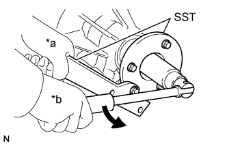
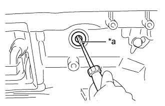
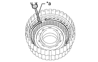
Text in Illustration *a Hold *b Turn Using SST and a 30 mm deep socket wrench, remove the lock nut.
- SST
- 09330-00021
- 09950-30012 ( 09955-03040 )
-
Remove SST.
-
Tap the automatic transmission flange yoke assembly with a plastic-faced hammer to remove it.
-
Remove the 2 rear No. 1 output shaft bearing spacers and rear cover sleeve.
-
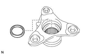
Using a screwdriver, pry out the oil seal from the automatic transmission flange yoke assembly.
Note
Do not damage the automatic transmission flange yoke assembly.
-
-
REMOVE AUTOMATIC TRANSMISSION OIL PAN SUB-ASSEMBLY
Note
Do not turn the automatic transmission assembly over as this will contaminate the transmission valve body assembly with foreign matter located at the bottom of the automatic transmission oil pan sub-assembly.
-
Remove the overflow plug and gasket.
-
Remove the drain plug and gasket.
-
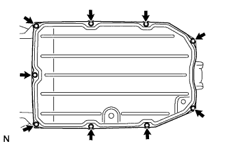
Remove the 9 bolts, automatic transmission oil pan sub-assembly and automatic transmission oil pan gasket.
-
Examine the particles in the automatic transmission oil pan sub-assembly.
-
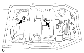
Remove the 3 transmission oil cleaner magnets from the automatic transmission oil pan sub-assembly. Use the removed 3 transmission oil cleaner magnets to collect any steel chips. Look carefully at the chips and particles in the automatic transmission oil pan sub-assembly and on the transmission oil cleaner magnet to anticipate the type of wear which might be found in the automatic transmission assembly.
Steel (magnetic): bearing, gear and plate wear
Brass (non-magnetic): bush wear
-
-
-
REMOVE VALVE BODY OIL STRAINER ASSEMBLY
-
Turn over the automatic transmission case sub-assembly.
-
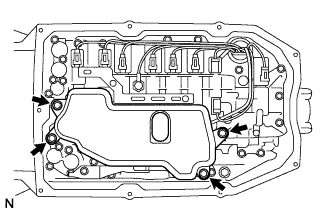
Remove the 4 bolts and valve body oil strainer assembly from the transmission valve body assembly.
-
Remove the O-ring from the valve body oil strainer.
-
-
REMOVE TRANSMISSION VALVE BODY ASSEMBLY
-
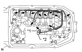
Text in Illustration *1 Lock Plate *2 ATF Temperature Sensor Remove the bolt, lock plate and ATF temperature sensor.
-
Remove the O-ring from the ATF temperature sensor.
-
Disconnect the oil pressure switch connector.
-
Disconnect the 9 shift solenoid valve connectors.
-
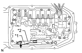
Text in Illustration *1 Detent Spring Cover *2 Detent Spring Remove the bolt, detent spring cover and detent spring.
-
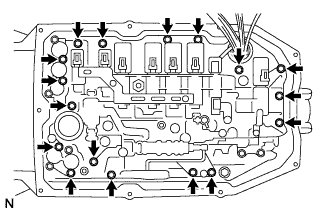
Remove the 17 bolts and transmission valve body assembly.
-
Text in Illustration *1 Manual Valve Connecting Rod *2 Manual Valve Lever Sub-assembly Disconnect the manual valve connecting rod from the manual valve lever sub-assembly.
-
-
REMOVE CHECK BALL BODY
-
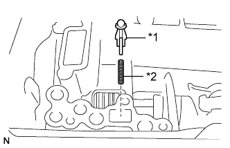
Text in Illustration *1 Check Ball Body *2 Spring Remove the check ball body and spring.
-
-
REMOVE TRANSMISSION WIRE
-
Disconnect the 3 connectors from the 3 transmission revolution sensors.
-
Remove the bolt and pull out the transmission wire.
-
Remove the O-ring from the transmission wire connector.
-
Remove the 2 bolts and 2 valve body wire harness clamps from the automatic transmission case sub-assembly.
-
-
REMOVE TRANSMISSION REVOLUTION SENSOR
-
Text in Illustration *1 Transmission Revolution Sensor NT *2 Transmission Revolution Sensor NC3 *3 Transmission Revolution Sensor SP2 Remove the 2 bolts and 2 transmission revolution sensors NC3 and SP2.
-
Using a T30 ''TORX'' socket wrench, remove the bolt and transmission revolution sensor NT from the oil pump assembly.
-
Remove the O-ring from the transmission revolution sensor NT.
-
-
REMOVE AUTOMATIC TRANSMISSION CASE PLUG
-

Remove the automatic transmission case plug and O-ring.
-
-
REMOVE PARKING LOCK PAWL BRACKET
-
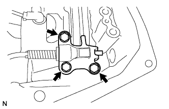
Remove the 3 bolts and parking lock pawl bracket.
-
-
REMOVE PARKING LOCK ROD SUB-ASSEMBLY
-
Disconnect the parking lock rod sub-assembly from the manual valve lever sub-assembly.
-
-
REMOVE PARKING LOCK PAWL SHAFT
-
Text in Illustration *1 Spring *2 Parking Lock Pawl Shaft *3 E-ring *4 Parking Lock Pawl Pull out the parking lock pawl shaft from the front side, and then remove the parking lock pawl and spring.
-
Remove the E-ring from the parking lock pawl shaft.
-
-
REMOVE MANUAL VALVE LEVER SUB-ASSEMBLY
-
Text in Illustration *a Protective Tape Using a screwdriver and hammer, cut off the spacer and remove it from the manual valve lever shaft.
Note
Be careful not to damage the manual valve lever shaft.
Tech Tips
Wrap the tip of the screwdriver with protective tape.
-
Using a 3 mm pin punch and hammer, tap out the spring pin.
Tech Tips
Slowly tap out the spring pin so that it does not fall into the automatic transmission case sub-assembly.
-
Pull the manual valve lever shaft out through the automatic transmission case sub-assembly, and remove the manual valve lever sub-assembly.
-
-
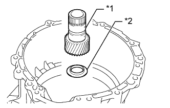
REMOVE MANUAL VALVE LEVER SHAFT OIL SEAL
-
Text in Illustration *a Protective Tape Using a screwdriver, pry out the manual valve lever shaft oil seal.
Note
Be careful not to damage the automatic transmission case sub-assembly.
Tech Tips
Wrap the tip of the screwdriver with protective tape.
-
-
REMOVE OIL PUMP ASSEMBLY
-
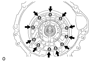
Remove the 11 bolts from the transmission case.
-
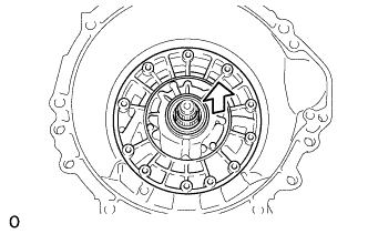
Pull out the oil pump assembly.
Note
Do not damage the oil pump assembly.
-
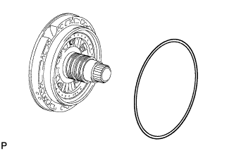
Remove the O-ring from the oil pump assembly.
-
-
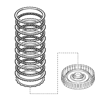
REMOVE OVERDRIVE DIRECT CLUTCH DRUM SUB-ASSEMBLY WITH FRONT PLANETARY GEAR ASSEMBLY AND NO. 1 BRAKE DISC SET
-
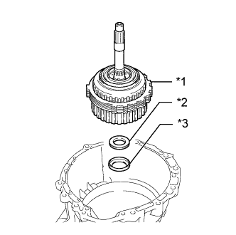
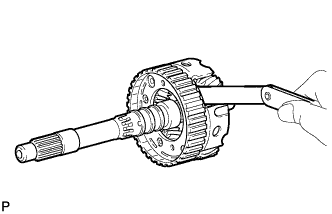
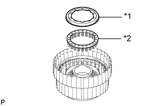
Text in Illustration *1 Overdrive Direct Clutch Drum Sub-assembly and Front Planetary Gear Assembly and No. 1 Brake Disc Set *2 Thrust Needle Roller Bearing *3 Thrust Bearing Race Remove the overdrive direct clutch drum sub-assembly with front planetary gear assembly and No. 1 brake disc set from the automatic transmission case sub-assembly.
-
Remove the thrust needle roller bearing and thrust bearing race.
-
-
REMOVE NO. 1 BRAKE DISC SET
-
Remove the 4 No. 1 brake plates, 4 No. 1 brake discs and No. 1 brake flange.
-
-
INSPECT NO. 1 BRAKE DISC
-
Check whether the sliding surfaces of the No. 1 brake discs, No. 1 brake plates and the No. 1 brake flange are worn or burnt.
If necessary, replace them.
Note
-
If the linings of the No. 1 brake discs are peeled off or discolored, or if any part of the printed numbers is damaged, replace all the No. 1 brake discs.
-
Before assembling new No. 1 brake discs, soak them in ATF for at least 2 hours.
-
-
-
REMOVE FRONT PLANETARY GEAR ASSEMBLY
-
Remove the front planetary gear assembly together with the planetary sun gear from the overdrive and reverse multiple disc clutch assembly.
-
Remove the planetary sun gear from the front planetary gear assembly.
-
Remove the planetary carrier thrust washer from the front planetary gear assembly.
-
Remove the 3 oil seal rings from the front planetary gear assembly.
-
Remove the 2 oil seal rings from the front planetary gear assembly.
-
Remove the front planetary gear thrust needle roller bearing from the front planetary gear assembly.
-
-
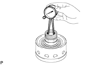
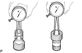
INSPECT FRONT PLANETARY GEAR ASSEMBLY
-
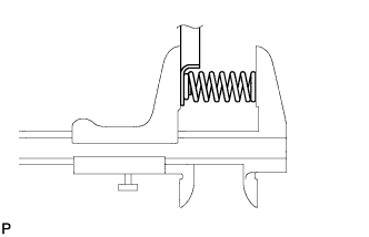
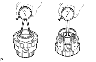
Using a feeler gauge, measure the front planetary gear pinion thrust clearance.
Standard clearance 0.2 to 0.6 mm (0.00788 to 0.0236 in.) If the inside diameter is more than the standard inside diameter, replace the rear planetary gear assembly.
-
-
REMOVE NO. 3 CLUTCH DISC SET
-
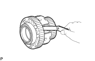
Text in Illustration *a Protective Tape Using a screwdriver, remove the snap ring from the overdrive direct clutch drum sub-assembly.
Note
Be careful not to damage the overdrive direct clutch drum sub-assembly.
Tech Tips
Wrap the tip of the screwdriver with protective tape.
-
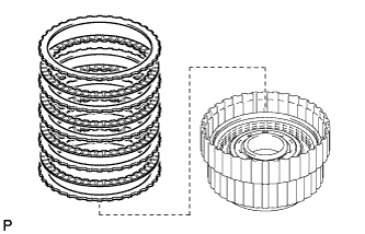
Remove the No. 3 clutch flange, 4 No. 3 clutch discs and 4 No. 3 clutch plates from the overdrive direct clutch drum sub-assembly.
-
-
INSPECT NO. 3 CLUTCH DISC
-
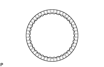
Check whether the sliding surfaces of the No. 3 clutch discs, No. 3 clutch plates and the No. 3 clutch flange are worn or burnt.
If necessary, replace them.
Note
Before assembling new No. 3 clutch discs, soak them in ATF for at least 2 hours.
-
-
REMOVE REVERSE CLUTCH DISC SET
-
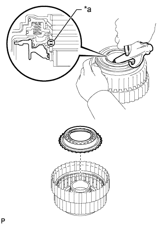
Text in Illustration *a Protective Tape Using a screwdriver, remove the snap ring from the reverse clutch drum sub-assembly.
Note
Be careful not to damage the reverse clutch drum sub-assembly.
Tech Tips
Wrap the tip of the screwdriver with protective tape.
-
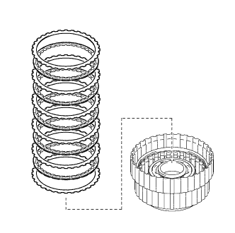
Remove the reverse clutch flange, 5 reverse clutch discs and 5 reverse clutch plates from the reverse clutch drum sub-assembly.
-
-
INSPECT REVERSE CLUTCH DISC
-
Check whether the sliding surfaces of the reverse clutch discs, reverse clutch plates and the reverse clutch flange are worn or burnt.
If necessary, replace them.
Note
-
If the linings of the reverse clutch discs are peeled off or discolored, or if any part of the printed numbers is damaged, replace all the reverse clutch discs.
-
Before assembling new reverse clutch discs, soak them in ATF for at least 2 hours.
-
-
-
REMOVE REVERSE CLUTCH PISTON
-
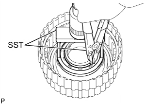
Place SST on the reverse clutch balancer, and compress the reverse clutch return spring sub-assembly with a press.
- SST
- 09380-50010 ( 09381-05020 )
-
Using SST, remove the snap ring.
- SST
- 09350-30020 ( 09350-07070 )
-
Text in Illustration *1 Reverse Clutch Balancer *2 Reverse Clutch Return Spring Sub-assembly Remove the reverse clutch balancer and reverse clutch return spring sub-assembly from the reverse clutch drum sub-assembly.
-
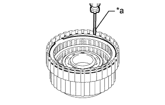
Text in Illustration *a Oil Hole Hold the clutch piston and apply compressed air to the oil hole of the reverse clutch drum to remove the reverse clutch piston.
-
Remove the O-ring from the reverse clutch piston.
-
-
INSPECT REVERSE CLUTCH RETURN SPRING SUB-ASSEMBLY
-
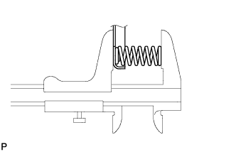
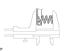
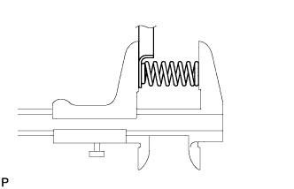
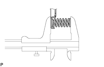
Using a vernier caliper, measure the free length of the spring together with the spring seat.
Standard free length 22.21 mm (0.874 in.) If the free length is shorter than the standard free length, replace the reverse clutch return spring sub-assembly.
-
-
REMOVE REVERSE CLUTCH DRUM SUB-ASSEMBLY
-
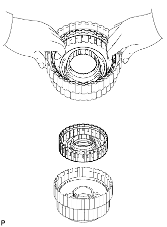
Remove the reverse clutch drum sub-assembly from the overdrive direct clutch drum sub-assembly.
Tech Tips
The reverse clutch drum sub-assembly is easier to remove if a snap ring is installed. Use the snap ring from the "REMOVE REVERSE CLUTCH DISC" procedure.
-
Remove the 3 O-rings from the reverse clutch drum sub-assembly.
-
-
REMOVE OVERDRIVE DIRECT CLUTCH PISTON SUB-ASSEMBLY
-
Place SST on the No. 3 clutch balancer, and compress the overdrive clutch return spring sub-assembly with a press.
- SST
- 09380-50010 ( 09381-05020 )
-
Using SST, remove the snap ring.
- SST
- 09350-30020 ( 09350-07070 )
-
Text in Illustration *1 No. 3 Clutch Balancer *2 Overdrive Clutch Return Spring Sub-assembly Remove the No. 3 clutch balancer and overdrive clutch return spring sub-assembly.
-
Remove the O-ring from the No. 3 clutch balancer.
-
Text in Illustration *a Oil Hole Hold the overdrive direct clutch piston sub-assembly and apply compressed air to the oil hole of the overdrive direct clutch drum sub-assembly to remove the overdrive direct clutch piston sub-assembly.
-
Remove the O-ring from the overdrive direct clutch piston sub-assembly.
-
Remove the O-ring from the overdrive direct clutch drum sub-assembly.
-
-
INSPECT OVERDRIVE CLUTCH RETURN SPRING SUB-ASSEMBLY
-
Using a vernier caliper, measure the free length of the spring together with the spring seat.
Standard free length 21.09 mm (0.830 in.) If the free length is shorter than the standard free length, replace the overdrive clutch return spring sub-assembly.
-
-
INSPECT OVERDRIVE DIRECT CLUTCH DRUM SUB-ASSEMBLY
-
Using a caliper gauge, measure the inside diameter of the overdrive direct clutch drum sub-assembly bush.
Standard inside diameter for front side 67.40 to 67.44 mm (2.6536 to 2.6551 in.) Standard inside diameter for rear side 55.62 to 55.64 mm (2.1898 to 2.1905 in.) If the inside diameter is not as specified, replace the overdrive direct clutch drum sub-assembly.
-
-
REMOVE FORWARD CLUTCH DRUM SUB-ASSEMBLY WITH FRONT PLANETARY RING GEAR
-
Text in Illustration *1 Forward Multiple Disc Clutch Assembly with Front Planetary Ring Gear *2 Thrust Needle Roller Bearing *3 Thrust Bearing Race Remove the forward multiple disc clutch assembly with front planetary ring gear, thrust needle roller bearing and thrust bearing race from the automatic transmission case sub-assembly.
-
-
REMOVE FRONT PLANETARY RING GEAR
-
Text in Illustration *1 Front Planetary Ring Gear *2 Snap Ring *3 Forward Clutch Drum Sub-assembly Using needle-nose pliers, detach the snap ring and remove the front planetary ring gear and snap ring from the forward clutch drum sub-assembly.
-
-
REMOVE FORWARD MULTIPLE CLUTCH DISC SET
-
Text in Illustration *a Protective Tape Using a screwdriver, remove the snap ring.
Note
Be careful not to damage the forward multiple disc clutch assembly.
Tech Tips
Wrap the tip of the screwdriver with protective tape.
-
Remove the forward clutch flange, 5 forward multiple clutch discs, 5 forward multiple clutch plates and clutch cushion plate.
-
-
INSPECT FORWARD MULTIPLE CLUTCH DISC
-
Check whether the sliding surfaces of the forward multiple clutch discs, forward multiple clutch plates, forward clutch flange and the clutch cushion plate are worn or burnt.
If necessary, replace them.
Note
-
If the linings of the forward multiple clutch discs are peeled off or discolored, or if any part of the printed numbers is damaged, replace all the forward multiple clutch discs.
-
Before assembling new forward multiple clutch discs, soak them in ATF for at least 2 hours.
-
-
-
REMOVE FORWARD CLUTCH PISTON
-
Place SST on the No. 1 clutch balancer, and compress the forward clutch return spring sub-assembly with a press.
- SST
- 09380-50010 ( 09381-05020 )
-
Using SST, remove the snap ring.
- SST
- 09350-30020 ( 09350-07070 )
-
Text in Illustration *1 No. 1 Clutch Balancer *2 Forward Clutch Return Spring Sub-assembly Remove the No. 1 clutch balancer and forward clutch return spring sub-assembly from the forward clutch drum sub-assembly.
-
Remove the O-ring from the No. 1 clutch balancer.
-

Text in Illustration *a Oil Hole Hold the forward clutch piston and apply compressed air to the oil hole of the forward clutch drum sub-assembly to remove the forward clutch piston.
-
Remove the 2 O-rings from the forward clutch piston.
-
-
INSPECT FORWARD CLUTCH RETURN SPRING SUB-ASSEMBLY
-
Using a vernier caliper, measure the free length of the spring together with the spring seat.
Standard free length 20.82 mm (0.820 in.) If the free length is shorter than the standard free length, replace the forward clutch return spring sub-assembly.
-
-
INSPECT FORWARD CLUTCH DRUM SUB-ASSEMBLY
-
Using a caliper gauge, measure the inside diameter of the forward clutch drum bush.
Standard inside diameter 33.200 to 33.225 mm (1.3071 to 1.3080 in.) If the inside diameter is not as specified, replace the forward clutch drum sub-assembly.
-
-
REMOVE MULTIPLE DISC CLUTCH HUB
-
Text in Illustration *1 Multiple Disc Clutch Hub *2 Thrust Bearing Race *3 Thrust Needle Roller Bearing Remove the multiple disc clutch hub from the transmission case.
-
Remove the thrust bearing race and thrust needle roller bearing from the automatic transmission case sub-assembly.
-
-
REMOVE SUN GEAR INPUT DRUM SUB-ASSEMBLY
-
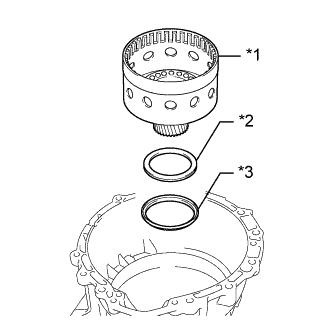
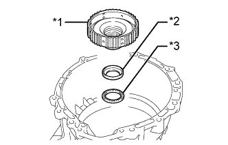
Text in Illustration *1 Sun Gear Input Drum Sub-assembly *2 Thrust Needle Roller Bearing *3 Thrust Bearing Race Remove the sun gear input drum sub-assembly, thrust needle roller bearing and thrust bearing race from the automatic transmission case sub-assembly.
-
-
INSPECT SUN GEAR INPUT DRUM SUB-ASSEMBLY
-
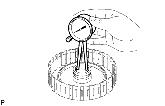
Using a caliper gauge, measure the inside diameter of the sun gear input drum bush.
Standard inside diameter 45.075 to 45.100 mm (1.7747 to 1.7755 in.) If the inside diameter is not as specified, replace the sun gear input drum sub-assembly.
-
-
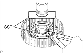
REMOVE ONE-WAY CLUTCH OUTER RACE WITH NO. 1 ONE-WAY CLUTCH
-
Using SST, remove the snap ring from the automatic transmission case sub-assembly.
- SST
- 09350-30020 ( 09350-07060 )
-
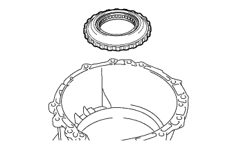
Remove the one-way clutch outer race with No. 1 one-way clutch.
-
-
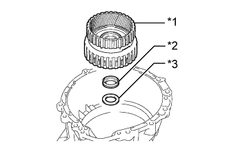
REMOVE REAR PLANETARY SUN GEAR ASSEMBLY
-
Text in Illustration *1 Rear Planetary Sun Gear Assembly *2 Thrust Bearing Race Remove the rear planetary sun gear assembly and thrust bearing race from the automatic transmission case sub-assembly.
-
-
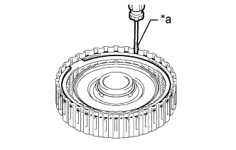
INSPECT REAR PLANETARY SUN GEAR ASSEMBLY
-
Using a caliper gauge, measure the inside diameter of the rear planetary sun gear bush.
Standard inside diameter 28.700 to 28.721 mm (1.1300 to 1.1307 in.) If the inside diameter is not as specified, replace the rear planetary sun gear assembly.
-
-
REMOVE REAR PLANETARY GEAR ASSEMBLY
-
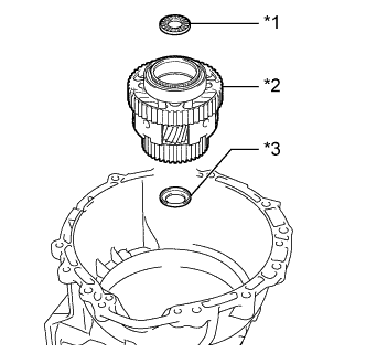
Text in Illustration *1 Thrust Needle Roller Bearing *2 Rear Planetary Gear Assembly *3 Thrust Bearing Race Remove the thrust needle roller bearing, rear planetary gear assembly and thrust bearing race from the automatic transmission case sub-assembly.
-
-
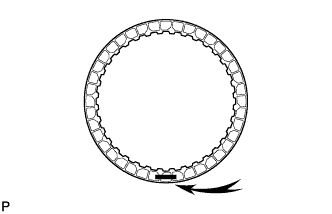
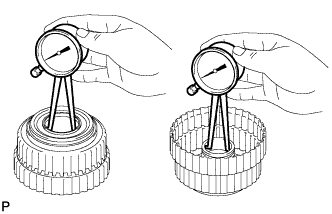
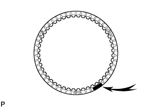
INSPECT NO. 1 ONE-WAY CLUTCH
-
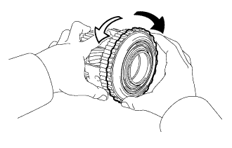
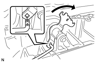
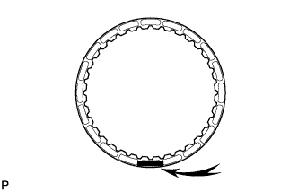
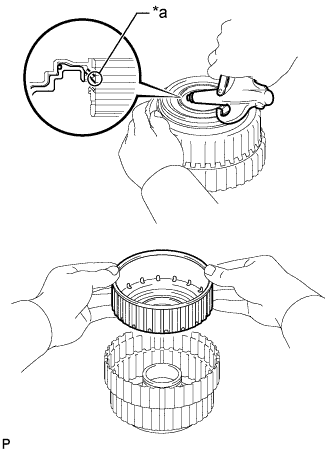
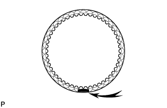
Set the one-way clutch to the rear planetary gear assembly.
Text in Illustration 
Lock 
Free -
Hold the rear planetary gear assembly and turn the one-way clutch.
-
Check that the one-way clutch turns freely counterclockwise and locks clockwise.
If there is a problem with the one-way clutch, replace it.
-
-
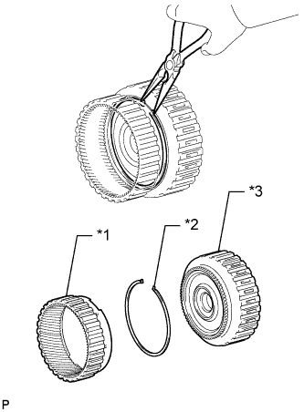
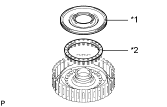
REMOVE NO. 1 ONE-WAY CLUTCH
-
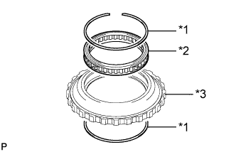
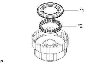
Text in Illustration *1 Snap Ring *2 No. 1 One-way Clutch *3 One-way Clutch Outer Race Remove the 2 snap rings and No. 1 one-way clutch from the one-way clutch outer race.
-
-
INSPECT REAR PLANETARY GEAR ASSEMBLY
-
Using a feeler gauge, measure the rear planetary gear pinion long and short thrust clearance.
Standard clearance 0.2 to 0.6 mm (0.00788 to 0.0236 in.) If the clearance is not as specified, replace the rear planetary gear assembly.
-
Using a caliper gauge, measure the inside diameter of the rear planetary gear bush.
Standard inside diameter for front side 71.60 to 71.63 mm (2.8189 to 2.8200 in.) Standard inside diameter for rear side 28.700 to 28.721 mm (1.1300 to 1.1307 in.) If the inside diameter is not as specified, replace the rear planetary gear assembly.
-
-
REMOVE NO. 2 BRAKE DISC SET
-
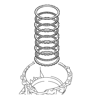
Remove the No. 2 brake No. 1 plate, 4 No. 2 brake discs, 3 No. 2 brake No. 2 plates and No. 2 brake flange.
-
-
INSPECT NO. 2 BRAKE DISC
-
Check whether the sliding surfaces of the No. 2 brake discs, No. 2 brake No. 1 plate, No. 2 brake No. 2 plates and the No. 2 brake flange are worn or burnt.
If necessary, replace them.
Note
-
If the linings of the No. 2 brake discs are peeled off or discolored, or if any part of the printed numbers is damaged, replace all the No. 2 brake discs.
-
Before assembling new discs, soak them in ATF for at least 2 hours.
-
-
-
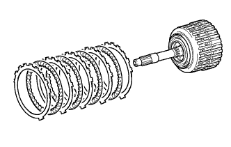
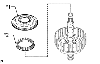
REMOVE DIRECT CLUTCH DRUM SUB-ASSEMBLY WITH REAR PLANETARY RING GEAR AND OUTPUT SHAFT SUB-ASSEMBLY
-
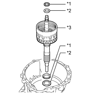
Text in Illustration *1 Thrust Needle Roller Bearing *2 Thrust Bearing Race *3 Direct Clutch Drum Sub-assembly with Rear Planetary Ring Gear and Output Shaft Sub-assembly Remove the 2 thrust needle roller bearings, 2 thrust bearing races, direct clutch drum sub-assembly with rear planetary ring gear and output shaft sub-assembly from the automatic transmission case sub-assembly.
-
-
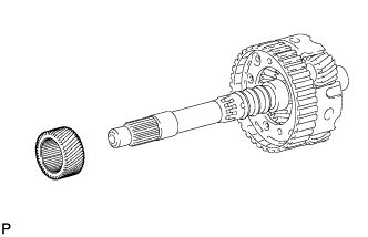
REMOVE REAR PLANETARY RING GEAR
-
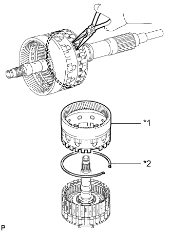
Text in Illustration *1 Rear Planetary Ring Gear *2 Snap Ring Using needle-nose pliers, detach the snap ring and remove the rear planetary ring gear from the output shaft sub-assembly.
-
-
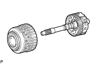
REMOVE DIRECT CLUTCH DRUM SUB-ASSEMBLY
-
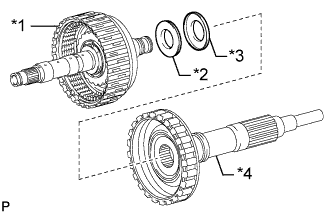
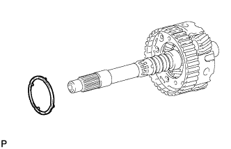
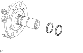
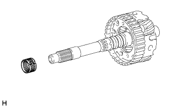
Text in Illustration *1 Direct Clutch Drum Sub-assembly *2 Thrust Needle Roller Bearing *3 Thrust Bearing Race *4 Output Shaft Sub-assembly Remove the direct clutch drum sub-assembly from the output shaft sub-assembly.
-
Remove the thrust needle roller bearing and thrust bearing race from the output shaft sub-assembly.
-
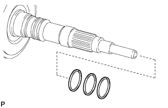
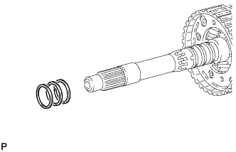
Remove the 3 oil seal rings from the output shaft sub-assembly.
-
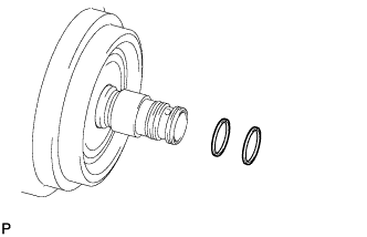
Remove the 2 oil seal rings from the direct clutch drum sub-assembly.
-
-
REMOVE NO. 2 CLUTCH DISC SET
-
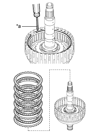
Text in Illustration *a Protective Tape Remove the snap ring and No. 2 clutch flange, 5 No. 2 clutch discs and 5 No. 2 clutch plates from the direct clutch drum sub-assembly.
Note
Be careful not to damage the direct clutch drum sub-assembly.
Tech Tips
Wrap the tip of the screwdriver with protective tape.
-
-
INSPECT NO. 2 CLUTCH DISC
-
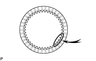
Check whether the sliding surfaces of the No. 2 clutch discs, No. 2 clutch plates and the No. 2 clutch flange are worn or burnt.
If necessary, replace them.
Note
-
If the linings of the No. 2 clutch discs are peeled off or discolored, or if any part of the printed numbers is damaged, replace all the No. 2 clutch discs.
-
Before assembling new discs, soak them in ATF for at least 2 hours.
-
-
-
REMOVE DIRECT CLUTCH PISTON
-
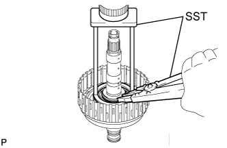
Place SST on the No. 2 clutch balancer, and compress the direct clutch return spring sub-assembly with a press.
- SST
- 09387-00020
-
Using SST, remove the snap ring.
- SST
- 09350-30020 ( 09350-07070 )
-
Text in Illustration *1 No. 2 Clutch Balancer *2 Direct Clutch Return Spring Sub-assembly Remove the No. 2 clutch balancer and direct clutch return spring sub-assembly from the direct clutch drum sub-assembly.
-
Remove the O-ring from the No. 2 clutch balancer.
-
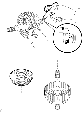
Text in Illustration *a Oil Hole Hold the direct clutch piston and apply compressed air to the oil hole of the direct clutch drum sub-assembly to remove the direct clutch piston.
-
Remove the O-ring from the direct clutch piston.
-
Remove the O-ring from the direct clutch drum sub-assembly.
-
-
INSPECT DIRECT CLUTCH RETURN SPRING SUB-ASSEMBLY
-
Using a vernier caliper, measure the free length of the spring together with the spring seat.
Standard free length 20.76 mm (0.817 in.) If the free length is shorter than the standard free length, replace the direct clutch return spring sub-assembly.
-
-
REMOVE NO. 2 BRAKE PISTON
-
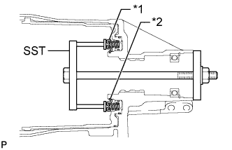
Text in Illustration *1 No. 2 Brake Piston Return Spring Sub-assembly *2 Snap Ring Set SST on the No. 2 brake piston return spring sub-assembly, tighten SST and compress the No. 2 brake piston return spring sub-assembly.
- SST
- 09380-50010 ( 09381-05010, 09381-05020 )
-
Using SST, remove the snap ring and the No. 2 brake piston return spring sub-assembly.
- SST
- 09350-30020 ( 09350-07070 )
-
Text in Illustration *a Oil Hole Hold the No. 2 brake piston and apply compressed air to the oil hole of the automatic transmission case sub-assembly to remove the No. 2 brake piston.
-
Remove the 3 O-rings from the No. 2 brake piston.
-
-
INSPECT NO. 2 BRAKE PISTON RETURN SPRING SUB-ASSEMBLY
-
Using a vernier caliper, measure the free length of the spring together with the spring seat.
Standard free length 23.36 mm (0.920 in.) If the free length is shorter than the standard free length, replace the No. 2 brake piston return spring sub-assembly.
-
-
REMOVE BRAKE PLATE STOPPER SPRING
-
Remove the 2 brake plate stopper springs.
-
-
REMOVE AUTOMATIC TRANSMISSION REAR OIL SEAL
-
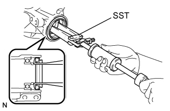
Using SST, tap out the automatic transmission rear oil seal.
- SST
- 09308-00010
-
-
REMOVE OUTPUT SHAFT REAR RADIAL BALL BEARING
-
Using snap ring pliers, remove the snap ring from the automatic transmission case sub-assembly.
-
Using SST, remove the output shaft rear radial ball bearing.
- SST
- 09308-00010
-