БЛОК АВТОМАТИЧЕСКОЙ ТРАНСМИССИИ ПРОВЕРКА

-
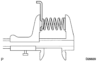
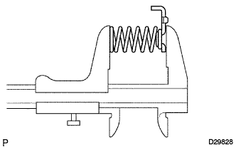
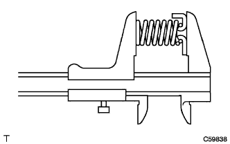
INSPECT 1ST AND REVERSE BRAKE RETURN SPRING SUB-ASSEMBLY
-
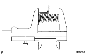
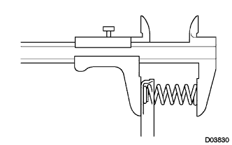
Using a vernier caliper, measure the free length of the spring together with the spring seat.
Standard free length 23.74 mm (0.935 in.) If the free length is less than the standard free length, replace the 1st and reverse brake return spring sub-assembly.
-
-
INSPECT REAR PLANETARY GEAR ASSEMBLY
-
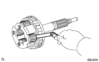
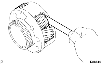
Using a feeler gauge, measure the rear planetary gear pinion thrust clearance.
Standard clearance 0.2 to 0.6 mm (0.00788 to 0.0236 in.) If the clearance is more than the standard clearance, replace the rear planetary gear assembly.
-
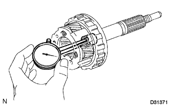
Using a caliper gauge, measure the inside diameter of the rear planetary gear bushing.
Standard inside diameter 20.025 mm (0.788 in.) If the inside diameter is more than the standard inside diameter, replace the rear planetary gear assembly.
-
-
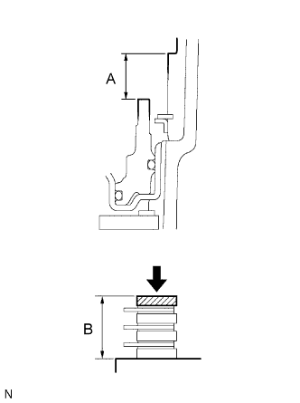
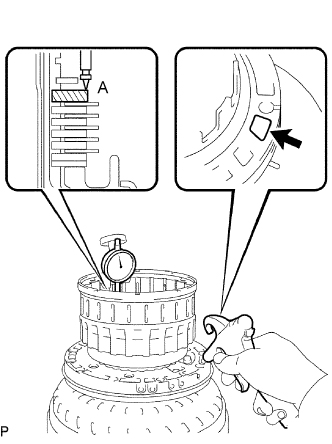
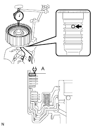
INSPECT PACK CLEARANCE OF 1ST AND REVERSE BRAKE PISTON
-
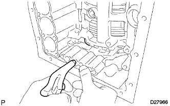
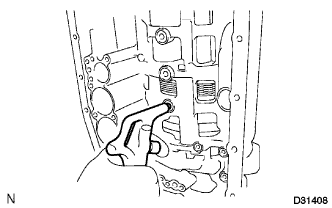
Make sure that the 1st and reverse brake piston moves smoothly when applying and releasing compressed air (392 kPa, 4.0 kgf/cm2, 57 psi).
If the 1st and reverse brake piston does not move smoothly, check the oil path of the transmission case, 1st and reverse brake piston and O-ring.
-
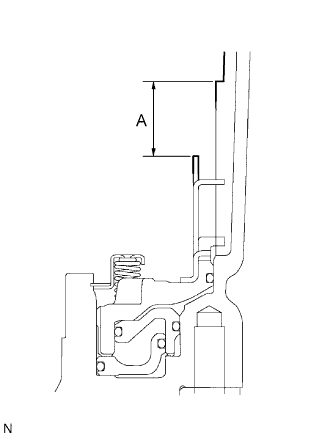
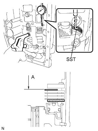
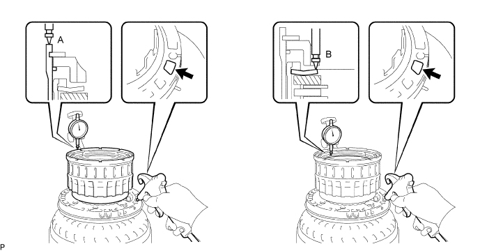
Using a vernier caliper, measure the level difference (dimension A) between the upper surface of the brake apply tube and the contact surface of the No. 4 brake flange at both ends across the 1st and reverse brake piston diameter, and calculate the average.
Note
The 1st and reverse brake piston must be securely installed to the end face of the transmission case.
Tech Tips
Dimension A = 22.05 to 22.91 mm (0.869 to 0.901 in.)
-
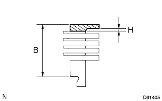
Using a vernier caliper and while applying compression of 4.9 N (0.5 kgf, 1.1 lbf) or less, measure the thickness (dimension B) of the No. 4 brake flange, 4 No. 4 brake plates and 4 No. 4 brake discs altogether at both ends across a diameter, and calculate the average.
Tech Tips
Dimension B = 23.11 to 23.89 mm (0.910 to 0.941 in.)
Pack Clearance = Dimension A - Dimension B - 0.22 mm (0.00866 in.) + 1.8 mm (0.0709 in.)
Pack clearance 0.4 to 0.7 mm (0.0158 to 0.0275 in.) -
If the pack clearance is outside the standard range, select and install a No. 4 brake flange that brings the pack clearance to be within the standard range.
Tech Tips
There are 11 types of No. 4 brake flanges that can be used to adjust the pack clearance. Select one with the most appropriate thickness.
Thickness H Part No. Mark Thickness H 35689-60270 0 0 mm (0 in.) 35689-60280 1 0.17 mm (0.00669 in.) 35689-60290 3 0.31 mm (0.0122 in.) 35689-60300 4 0.45 mm (0.0177 in.) 35689-60310 5 0.59 mm (0.0232 in.) 35689-60320 7 0.73 mm (0.0287 in.) 35689-60330 8 0.87 mm (0.0343 in.) 35689-60340 10 1.01 mm (0.0398 in.) 35689-60350 11 1.15 mm (0.0453 in.) 35689-60360 12 1.29 mm (0.0508 in.) 35689-60370 14 1.43 mm (0.0563 in.)
-
-
INSPECT NO. 4 BRAKE DISC
-
Check whether the sliding surfaces of the discs, plates or flange are worn or burnt.
If necessary, replace them.
Note
-
If the linings of the discs are peeled off or discolored, or if any part of the printed numbers is damaged, replace all discs.
-
Before assembling new discs, soak them in ATF for at least 15 minutes.
-
-
-
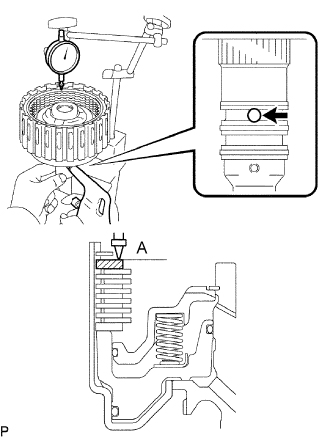
INSPECT INTERMEDIATE SHAFT
-
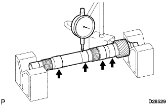
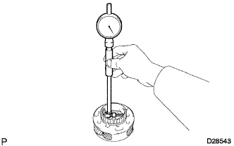
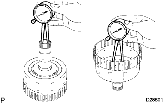
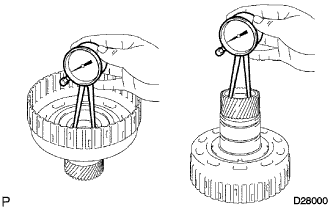
Using a dial indicator, check the intermediate shaft runout.
Standard runout 0.03 mm (0.00118 in.) If the runout exceeds the specification, replace the intermediate shaft with a new one.
-
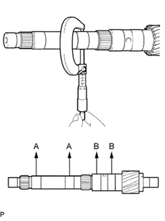
Using a micrometer, check the outer diameter of the intermediate shaft at each point shown in the illustration.
Standard diameter A 25.962 to 25.975 mm (1.02213 to 1.02263 in.) B 32.062 to 32.075 mm (1.26228 to 1.26279 in.) If the outer diameter is outside the standard range, replace the intermediate shaft with a new one.
-
-
INSPECT REAR PLANETARY RING GEAR FLANGE SUB-ASSEMBLY
-
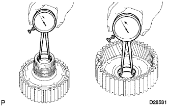
Using a caliper gauge, measure the inside diameter of the rear planetary ring gear bushing.
Standard inside diameter 32.19 mm (1.27 in.) If the inside diameter is more than the standard inside diameter, replace the rear planetary ring gear flange sub-assembly.
-
-
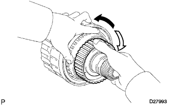
INSPECT NO. 3 ONE-WAY CLUTCH ASSEMBLY
-
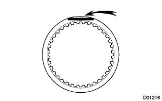
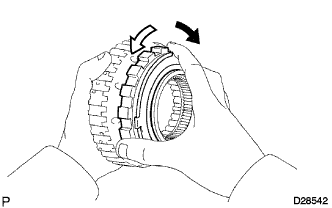
Hold the rear planetary ring gear flange sub-assembly and turn the No. 3 one-way clutch assembly.
-
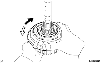
Check that the No. 3 one-way clutch assembly turns freely counterclockwise and locks clockwise.
Text in Illustration 
Lock 
Free If there is a problem with the No. 3 one-way clutch assembly, replace the No. 3 one-way clutch assembly.
-
-
INSPECT CENTER PLANETARY GEAR ASSEMBLY
-
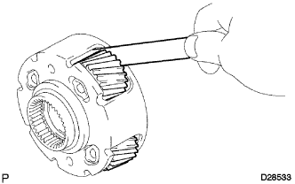
Using a feeler gauge, measure the center planetary gear pinion thrust clearance.
Standard clearance 0.12 to 0.68 mm (0.00473 to 0.02677 in.) If the clearance is more than the standard clearance, replace the center planetary gear assembly.
-
-
INSPECT NO. 2 BRAKE DISC
-
Check whether the sliding surfaces of the discs, plates or flange are worn or burnt.
If necessary, replace them.
Note
-
If the linings of the discs are peeled off or discolored, or if any part of the printed numbers is damaged, replace all discs.
-
Before assembling new discs, soak them in ATF for at least 15 minutes.
-
-
-
INSPECT NO. 2 BRAKE PISTON RETURN SPRING SUB-ASSEMBLY
-
Using a vernier caliper, measure the free length of the spring together with the spring seat.
Standard free length 22.66 mm (0.892 in.) If the free length is less than the standard free length, replace the No. 2 brake piston return spring sub-assembly.
-
-
INSPECT NO. 2 BRAKE PISTON
-
Inspect piston stroke of the No. 2 brake piston.
-
Make sure that the No. 2 brake piston moves smoothly when applying and releasing compressed air (392 kPa, 4.0 kgf/cm2, 57 psi).
If the No. 2 brake piston does not move smoothly, check the oil path of the transmission case, No. 2 brake piston and O-rings.
-
Using SST and a dial indicator, measure the moving distance (distance A) of the No. 2 brake disc at both ends across a diameter while blowing air (392 kPa, 4.0 kgf/cm2, 57 psi) into the oil hole as shown in the illustration, and calculate the average.
- SST
- 09350-30020 ( 09350-06120 )
Piston stroke 0.6 to 0.9 mm (0.0237 to 0.0354 in.) -
If the piston stroke is outside the standard range, select and install a No. 2 brake flange that brings the piston stroke within the standard range.
Tech Tips
There are 8 types of No. 2 brake flanges that can be used to adjust the piston stroke. Select one with the most appropriate thickness.
Flange Thickness Part No. Mark Thickness 35678-60020 0 2.0 mm (0.0787 in.) 35678-60030 1 2.1 mm (0.0827 in.) 35678-60040 2 2.2 mm (0.0866 in.) 35678-60050 3 2.3 mm (0.0906 in.) 35678-60060 4 2.4 mm (0.0945 in.) 35678-60070 5 2.5 mm (0.0984 in.) 35678-60080 6 2.6 mm (0.102 in.) 35678-60090 7 2.7 mm (0.106 in.)
-
-
-
INSPECT BRAKE PISTON RETURN SPRING SUB-ASSEMBLY
-
Using a vernier caliper, measure the free length of the spring together with the spring seat.
Standard free length 17.05 mm (0.671 in.) If the free length is less than the standard free length, replace the brake piston return spring sub-assembly.
-
-
INSPECT FRONT PLANETARY GEAR ASSEMBLY
-
Using a feeler gauge, measure the front planetary pinion gear thrust clearance.
Standard clearance 0.20 to 0.60 mm (0.00788 to 0.0236 in.) If the clearance is more than the standard clearance, replace the front planetary gear assembly.
-
Using a cylinder gauge, measure the inside diameter of the front planetary gear bushing.
Standard inside diameter 57.43 mm (2.26 in.) If the inside diameter is more than the standard inside diameter, replace the front planetary gear assembly.
-
-
INSPECT ONE-WAY CLUTCH ASSEMBLY
-
Install the one-way clutch assembly to the one-way clutch inner race.
-
Hold the one-way clutch inner race and turn the one-way clutch assembly.
-
Check that the one-way clutch assembly turns freely counterclockwise and locks clockwise.
Text in Illustration Lock Free If there is a problem with the one-way clutch, replace the one-way clutch assembly.
-
Remove the one-way clutch assembly from the one-way clutch inner race.
-
-
INSPECT NO. 1 BRAKE PISTON
-
Inspect piston stroke of the No. 1 brake piston.
-
Make sure that the No. 1 brake piston moves smoothly when applying and releasing compressed air (392 kPa, 4.0 kgf/cm2, 57 psi).
If the No. 1 brake piston does not move smoothly, check the oil path of the transmission case, No. 1 brake piston and O-rings.
-
Using a vernier caliper, and while applying compression of 4.9 N (0.5 kgf, 1.1 lbf) or less, measure the level difference (dimension A) between the upper surface of the No. 1 brake piston and the contact surface of the No. 1 brake flange at both ends across the No. 1 brake piston diameter.
-
Using a vernier caliper, measure the thickness (dimension B) of the No. 1 brake flange, 3 No. 1 brake plates and 3 No. 1 brake discs altogether at both ends across a diameter, and calculate the average.
Tech Tips
Dimension A = 15.29 to 15.77 mm (0.602 to 0.621 in.)
Dimension B = 14.72 to 15.12 mm (0.580 to 0.595 in.)
Piston stroke = Dimension A - Dimension B
Piston stroke 0.42 to 0.72 mm (0.0166 to 0.0283 in.) If the piston stroke is outside the specified range, parts may have been assembled incorrectly, so check and reassemble them again.
If the piston stroke is still outside the standard range, select another No. 1 brake flange that brings the piston stroke within the standard range.
Tech Tips
There are 4 different thicknesses for the No. 1 brake flange that bring the piston stroke within the specified range.
Flange Thickness Part No. Mark Thickness 35676-60080 0 2.0 mm (0.0787 in.) 35676-60090 1 2.2 mm (0.0866 in.) 35676-60100 2 2.4 mm (0.0945 in.) 35676-60110 3 2.6 mm (0.102 in.)
-
-
-
INSPECT NO. 1 BRAKE DISC
-
Check whether the sliding surfaces of the discs, plates or flange are worn or burnt.
If necessary, replace them.
Note
-
If the linings of the discs are peeled off or discolored, or if any part of the printed numbers is damaged, replace all discs.
-
Before assembling new discs, soak them in ATF for at least 15 minutes.
-
-
-
INSPECT NO. 3 BRAKE PISTON RETURN SPRING SUB-ASSEMBLY
-
Using a vernier caliper, measure the free length of the spring together with the spring seat.
Standard free length 15.72 mm (0.619 in.) If the inside diameter is less than the standard free length, replace the No. 3 brake piston return spring sub-assembly.
-
-
INSPECT NO. 3 BRAKE DISC
-
Check whether the sliding surfaces of the discs, plates or flange are worn or burnt.
If necessary, replace them.
Note
-
If the linings of the discs are peeled off or discolored, or if any part of the printed numbers is damaged, replace all discs.
-
Before assembling new discs, soak them in ATF for at least 15 minutes.
-
-
-
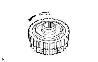
INSPECT NO. 2 ONE-WAY CLUTCH ASSEMBLY
-
Hold the reverse clutch hub and turn the No. 2 one-way clutch assembly.
-
Check that the No. 2 one-way clutch assembly turns freely clockwise and locks counterclockwise.
Text in Illustration Lock Free If there is a problem with the one-way clutch, replace the No. 2 one-way clutch assembly.
-
-
INSPECT INDIVIDUAL PISTON OPERATION
-

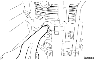
Text in Illustration *1 No. 1 Clutch *2 No. 2 Clutch *3 No. 3 Clutch *4 No. 4 Clutch *5 No. 1 Brake *6 No. 2 Brake *7 No. 3 Brake *8 No. 4 Brake (In) *9 No. 4 Brake (Out) Check the operating sound while applying compressed air into the oil holes indicated in the illustration.
Tech Tips
When inspecting the O/D direct clutch, check the operating sound with the C3 accumulator piston hole closed.
If there is no sound, disassemble and check the installation condition of the parts.
-
No. 2 Clutch (C2)
-
No. 4 Clutch (C4)
-
No. 3 Clutch (C3)
-
No. 1 Clutch (C1)
-
No. 3 Brake (B3)
-
No. 1 Brake (B1)
-
No. 2 Brake (B2)
-
No. 4 Brake (B4)
-
-
-
INSPECT UNDERDRIVE ONE-WAY CLUTCH ASSEMBLY
-
Hold the coast clutch hub and turn the underdrive one-way clutch assembly.
-
Check that the underdrive one-way clutch assembly turns freely clockwise and locks counterclockwise.
Text in Illustration Lock Free If there is a problem with the underdrive one-way clutch assembly, replace underdrive one-way clutch assembly.
-
-
INSPECT DIRECT CLUTCH RETURN SPRING SUB-ASSEMBLY
-
Using a vernier caliper, measure the free length of the spring together with the spring seat.
Standard free length 19.51 mm (0.768 in.) If the free length is less than the standard free length, replace the direct clutch return spring sub-assembly.
-
-
INSPECT REVERSE CLUTCH RETURN SPRING SUB-ASSEMBLY
-
Using a vernier caliper, measure the free length of the spring together with the spring seat.
Standard free length 21.04 mm (0.828 in.) If the free length is less than the standard free length, replace the reverse clutch return spring sub-assembly.
-
-
INSPECT NO. 2 DIRECT CLUTCH DISC
-
Check whether the sliding surfaces of the discs, plates or flange are worn or burnt.
If necessary, replace them.
Note
-
If the linings of the discs are peeled off or discolored, or if any part of the printed numbers is damaged, replace all discs.
-
Before assembling new discs, soak them in ATF for at least 15 minutes.
-
-
-
INSPECT PACK CLEARANCE OF NO. 2 DIRECT CLUTCH
-
Inspect the pack clearance of the No. 2 direct clutch.
-
Using a dial indicator, measure the moving distance (distance A) of the direct clutch flange at both ends across a diameter while blowing air (392 kPa, 4.0 kgf/cm2, 57 psi) into the oil hole as shown in the illustration, and calculate the average.
Tech Tips
Flange moving distance A = 0.36 to 1.24 mm (0.0142 to 0.0488 in.)
Pack clearance = Flange moving distance A - 0.05 mm (0.00197 in.)
Pack clearance 0.5 to 0.8 mm (0.0197 to 0.0314 in.) Note
Install a selective flange {t = 3.4 mm (0.1339 in.)} when measuring the moving distance (shaded area in the illustration).
-
If the pack clearance is outside the specified range, select and install a reverse clutch flange that brings the pack clearance within the specified range.
Tech Tips
There are 9 types of reverse clutch flanges that can be used to adjust the pack clearance. Select one with the most appropriate thickness.
Flange Thickness Part No. Mark Thickness 35649-60030 0 3.0 mm (0.118 in.) 35649-60040 1 3.1 mm (0.122 in.) 35649-60050 2 3.2 mm (0.126 in.) 35649-60060 3 3.3 mm (0.130 in.) 35649-60070 4 3.4 mm (0.134 in.) 35649-60080 5 3.5 mm (0.138 in.) 35649-60090 6 3.6 mm (0.142 in.) 35649-60100 7 3.7 mm (0.146 in.) 35649-60110 8 3.8 mm (0.150 in.)
-
-
-
INSPECT PACK CLEARANCE OF NO. 3 CLUTCH
-
Inspect the pack clearance of the No. 3 clutch.
-
Using a dial indicator, measure the reverse clutch piston stroke (distance A) and the moving distance (distance B) of the reverse clutch flange at both ends across a diameter while blowing air (392 kPa, 4.0 kgf/cm2, 57 psi) from the oil hole as shown in the illustration, and calculate the average.
Tech Tips
Piston stroke A = 1.05 to 2.15 mm (0.0413 to 0.0846 in.)
Flange moving distance B = 0.72 to 1.08 mm (0.0283 to 0.0425 in.)
Pack clearance = Piston stroke A - Flange moving distance B - 0.06 mm (0.00236 in.)
Pack clearance 0.5 to 0.8 mm (0.0197 to 0.0314 in.) Note
Install a selective flange {t = 3.3 mm (0.130 in.)} when measuring the moving distance (shaded area in the illustration).
-
If the pack clearance is outside the specified range, select and install a reverse clutch flange that brings the pack clearance within the specified range.
Tech Tips
There are 11 types of reverse clutch flanges that can be used to adjust the pack clearance. Select one with the most appropriate thickness.
Flange Thickness Part No. Mark Thickness 35649-60010 0 2.8 mm (0.110 in.) 35649-60020 1 2.9 mm (0.114 in.) 35649-60030 2 3.0 mm (0.118 in.) 35649-60040 3 3.1 mm (0.122 in.) 35649-60050 4 3.2 mm (0.126 in.) 35649-60060 5 3.3 mm (0.130 in.) 35649-60070 6 3.4 mm (0.134 in.) 35649-60080 7 3.5 mm (0.138 in.) 35649-60090 8 3.6 mm (0.142 in.) 35649-60100 9 3.7 mm (0.146 in.) 35649-60110 A 3.8 mm (0.150 in.)
-
-
-
INSPECT FORWARD CLUTCH RETURN SPRING SUB-ASSEMBLY
-
Using a vernier caliper, measure the free length of the spring together with the spring seat.
Standard free length 24.64 mm (0.970 in.) If the free length is less than the standard free length, replace the forward clutch return spring sub-assembly.
-
-
INSPECT COAST CLUTCH DISC
-
Check whether the sliding surfaces of the discs, plates or flange are worn or burnt.
If necessary, replace them.
Note
-
If the linings of the discs are peeled off or discolored, or if any part of the printed numbers is damaged, replace all discs.
-
Before assembling new discs, soak them in ATF for at least 15 minutes.
-
-
-
INSPECT PACK CLEARANCE OF COAST CLUTCH
-
Inspect the pack clearance of the coast clutch hub sub-assembly.
-
Using a dial indicator, measure the moving distance (distance A) of the coast clutch flange at both ends across a diameter while blowing air (196 kPa, 2.0 kgf/cm2, 28 psi) into the oil hole as shown in the illustration, and calculate the average.
Tech Tips
Flange moving distance A = 0.38 to 1.48 mm (0.0150 to 0.0582 in.)
Pack clearance = Flange moving distance A - 0.02 mm (0.000787 in.)
Pack clearance 0.3 to 0.6 mm (0.0119 to 0.0236 in.) Note
Install a selective flange {t = 3.0 mm (0.118 in.)} when measuring the moving distance (shaded area in the illustration).
-
If the pack clearance is outside the specified range, select and install a reverse clutch flange that brings the pack clearance within the specified range.
Tech Tips
There are 10 types of reverse clutch flanges that can be used to adjust the pack clearance. Select one with the most appropriate thickness.
Flange Thickness Part No. Mark Thickness 35675-50010 1 3.0 mm (0.118 in.) 35675-50020 2 3.1 mm (0.122 in.) 35675-50030 3 3.2 mm (0.126 in.) 35675-50040 4 3.3 mm (0.130 in.) 35675-50050 5 3.4 mm (0.134 in.) 35675-50060 6 3.5 mm (0.138 in.) 35675-50070 7 3.6 mm (0.142 in.) 35675-50080 8 3.7 mm (0.146 in.) 35675-50090 9 3.8 mm (0.150 in.) 35675-50100 A 3.9 mm (0.154 in.)
-
-
-
INSPECT NO. 1 CLUTCH DISC
-
Check whether the sliding surfaces of the discs, plates or flange are worn or burnt.
If necessary, replace them.
Note
-
If the linings of the discs are peeled off or discolored, or if any part of the printed numbers is damaged, replace all discs.
-
Before assembling new discs, soak them in ATF for at least 15 minutes.
-
-
-
INSPECT PACK CLEARANCE OF NO. 1 CLUTCH
-
Inspect the pack clearance of the No. 1 clutch.
-
Using a dial indicator, measure the moving distance (distance A) of the forward clutch flange at both ends across a diameter while blowing air (196 kPa, 2.0 kgf/cm2, 28 psi) into the oil hole as shown in the illustration, and calculate the average..
Tech Tips
Flange moving distance A = 0.36 to 1.50 mm (0.0142 to 0.0590 in.)
Pack clearance = Flange moving distance A - 0.11 mm (0.00433 in.)
Pack clearance 0.56 to 0.86 mm (0.0221 to 0.0338 in.) Note
Install a selective flange {t = 3.4 mm (0.134 in.)} when measuring the moving distance (shaded area in the illustration).
-
If the pack clearance is outside the specified range, select and install a reverse clutch flange that brings the pack clearance within the specified range.
Tech Tips
There are 11 types of reverse clutch flanges that can be used to adjust the pack clearance. Select one with the most appropriate thickness.
Flange Thickness Part No. Mark Thickness 35635-60010 0 3.0 mm (0.118 in.) 35635-60020 1 3.1 mm (0.122 in.) 35635-60030 2 3.2 mm (0.126 in.) 35635-60040 3 3.3 mm (0.130 in.) 35635-60050 4 3.4 mm (0.134 in.) 35635-60060 5 3.5 mm (0.138 in.) 35635-60070 6 3.6 mm (0.142 in.) 35635-60080 7 3.7 mm (0.146 in.) 35635-60090 8 3.8 mm (0.150 in.) 35635-60100 9 3.9 mm (0.154 in.) 35635-60110 A 4.0 mm (0.158 in.)
-
-
-
INSPECT CLUTCH HUB SUB-ASSEMBLY
-
Using a caliper gauge, measure the inside diameter of the clutch hub bushing.
Standard inside diameter 26.037 to 26.062 mm (1.02508 to 1.02606 in.) If the inside diameter is more than the standard inside diameter, replace the clutch hub sub-assembly.
-
-
INSPECT NO. 3 CLUTCH DISC
-
Check whether the sliding surfaces of the discs, plates or flange are worn or burnt.
If necessary, replace them.
Note
-
If the linings of the discs are peeled off or discolored, or if any part of the printed numbers is damaged, replace all discs.
-
Before assembling new discs, soak them in ATF for at least 15 minutes.
-
-
-
INSPECT REVERSE CLUTCH HUB SUB-ASSEMBLY
-
Using a caliper gauge, measure the inside diameter of the reverse clutch hub bushing.
Standard inside diameter 35.812 to 35.837 mm (1.4100 to 1.41090 in.) If the inside diameter is more than the standard inside diameter, replace the reverse clutch hub sub-assembly.
-