HEADLIGHT ASSEMBLY (for HID Headlight) DISASSEMBLY

Tech Tips
-
Use the same procedure for the RH and LH sides.
-
The procedure described below is for the LH side.
-
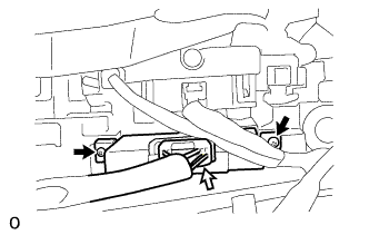
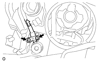
REMOVE FRONT TURN SIGNAL LIGHT SOCKET
-
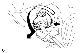
Disconnect the connector.
-
Turn the front turn signal light socket in the direction indicated by the arrow in the illustration and remove the front turn signal light socket.
-
-
REMOVE FRONT TURN SIGNAL LIGHT BULB
-
Remove the front turn signal light bulb from the front turn signal light socket.
-
-
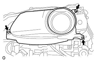
REMOVE HEADLIGHT LIGHT CONTROL ECU SUB-ASSEMBLY LH
-
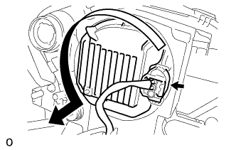
Disconnect the connector.
-
Turn the headlight light control ECU sub-assembly LH in the direction indicated by the arrow in the illustration and separate the headlight light control ECU sub-assembly LH from the headlight unit.
Note
-
Do not apply excessive force using a tool.
-
Do not damage the headlight gasket or allow it to become contaminated with foreign matter. If the headlight gasket is damaged or contaminated, water may get into the headlight assembly, resulting in a malfunction of the headlight light control ECU sub-assembly LH.
-
-
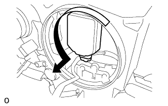
Turn the headlight light control ECU sub-assembly LH socket in the direction indicated by the arrow in the illustration and disconnect the headlight light control ECU sub-assembly LH socket to remove the headlight light control ECU sub-assembly LH.
Note
Do not pull the headlight light control ECU subassembly LH with the socket connected.
-
-
REMOVE HEADLIGHT GASKET
-
Remove the headlight gasket from the headlight light control ECU sub-assembly LH.
-
-
REMOVE DISCHARGE HEADLIGHT BULB
-
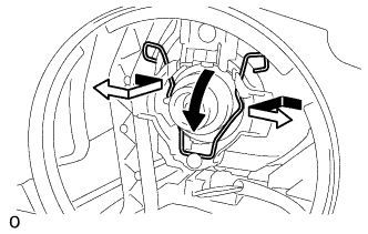
Release the set spring lock as shown in the illustration and remove the discharge headlight bulb.
Note
Do not touch the discharge headlight bulb glass.
-
-
REMOVE FRONT BUMPER SIDE SUPPORT LH
-
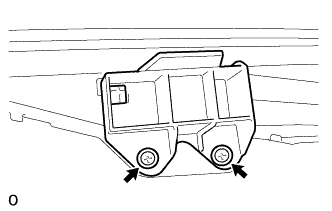
Remove the 2 screws and front bumper side support LH from the headlight unit.
-
-
REMOVE NO. 2 FRONT BUMPER SIDE SUPPORT LH
-
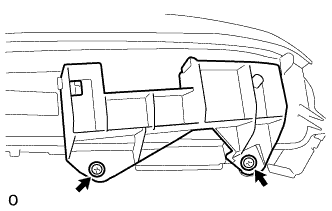
Remove the 2 screws and No. 2 front bumper side support LH from the headlight unit.
-
-
REMOVE HEADLIGHT LENS LH
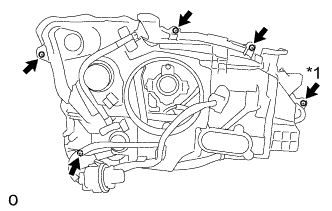
-
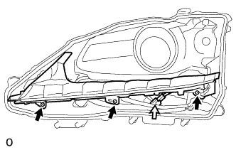
Using a T20H "TORX" driver, remove the "TORX" screw.
-
Remove the 4 screws.
Text in Illustration *1 "TORX" Screw -
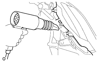
Using a dryer, heat the backside of the headlight unit.
Note
If the headlight is heated unevenly, it will deform or melt.
-
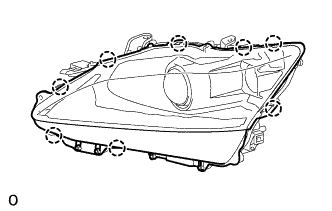
Detach the 8 claws and remove the headlight lens LH from the headlight unit.
Note
-
Wear rubber gloves when handling the headlight lens LH.
-
Do not touch the headlight lens LH or the aluminum surfaces with bare hands.
-
If there are fingerprints on the aluminum surfaces, wipe them off with a soft cloth.
-
If there are fingerprints on the back of the lens, replace the headlight lens LH.
-
Do not allow dirt or foreign matter on the headlight lens LH.
Tech Tips
If the lens cannot be removed even after heating, using a screwdriver with its tip wrapped in tape, lift the lens. Be careful not to damage the headlight unit and headlight lens LH.
-
-
-
REMOVE HEADLIGHT LENS GASKET
-
Remove the headlight lens gasket from the headlight unit.
-
-
REMOVE HEADLIGHT UNIT LH
-
Remove the 3 screws and headlight unit LH from the headlight unit.
Text in Illustration 
Screw 
Connector Note
-
Do not touch the headlight unit LH or the aluminum surfaces with bare hands.
-
If there are fingerprints on the aluminum surfaces, wipe them off with a soft cloth.
-
-
Disconnect the connector.
-
-
REMOVE LIGHT CONTROL ECU
-
Remove the 2 screws and light control ECU from the headlight unit.
Text in Illustration Screw Connector -
Connect the connector.
-
-
REMOVE HEADLIGHT SWIVEL MOTOR LH
-
Remove the 3 screws and aluminum surfaces from the headlight unit.
Note
-
Do not touch the aluminum surfaces with bare hands.
-
If there are fingerprints on the aluminum surfaces, wipe them off with a soft cloth.
-
-
Remove the 2 screws and the plate, and remove the connected gears from the aiming screw.
Text in Illustration Screw Cable -
Connect the connector.
Text in Illustration Screw Connector -
Remove the screw.
-
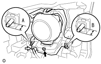
Before removing the headlight swivel motor LH, measure dimensions A and B in the diagram and take a note.
-
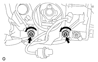
Rotate the 2 aiming screws counterclockwise.
-
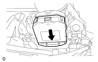
Move the headlight swivel motor LH as shown in the illustration and remove it from the headlight unit.
-