LIGHTING SYSTEM TERMINALS OF ECU

-
CHECK HEADLIGHT SWIVEL ECU ASSEMBLY

-
Disconnect the A7 headlight swivel ECU connector.
-
Measure the resistance and voltage according to the value(s) in the table below.
Terminal No. (Symbol) Wiring Color Terminal Description Condition Specified Condition A7-14 (IGS) - Body ground LG - Body ground Ignition power supply Engine switch off Below 1 V Engine switch on (IG) 11 to 14 V A7-15 (IG) - Body ground L - Body ground Ignition power supply Engine switch off Below 1 V Engine switch on (IG) 11 to 14 V A7-22 (E1) - Body ground W-B - Body ground Ground Always Below 1 Ω If the result is not as specified, there may be a malfunction on the wire harness side.
-
Reconnect the A7 headlight swivel ECU connector.
-
Measure the voltage according to the value(s) in the table below.
Terminal No. (Symbol) Wiring Color Terminal Description Condition Specified Condition A7-1 (SMBL) - A7-22 (E1)*1 SB - W-B Headlight swivel motor LH power supply Engine switch off Below 1 V Engine switch on (IG) 11 to 14 V A7-2 (SMBR) - A7-22 (E1)*1 B - W-B Headlight swivel motor RH power supply Engine switch off Below 1 V Engine switch on (IG) 11 to 14 V A7-3 (LHT) - A7-22 (E1)*2 V - W-B Headlight swivel motor LH (leveling portion) power supply Engine switch off Below 1 V Engine switch on (IG) 11 to 14 V A7-4 (RHT) - A7-22 (E1)*2 G - W-B Headlight swivel motor RH (leveling portion) power supply Engine switch off Below 1 V Engine switch on (IG) 11 to 14 V A7-7 (INIT) - A7-22 (E1) V - W-B Initialization signal Engine switch on (IG), terminals LVL and GND of DLC3 connected Below 1 V Engine switch on (IG), terminals LVL and GND of DLC3 not connected 4.5 to 5.5 V A7-10 (SMR) - A7-22 (E1)*1 W - W-B Headlight swivel motor RH LIN communication Engine switch off Below 1 V Engine switch on (IG) Pulse generation A7-11 (RH+) - A7-22 (E1) P - W-B Headlight swivel motor RH (leveling portion) LIN communication Engine switch off Below 1 V Engine switch on (IG) Pulse generation A7-18 (SBR) - A7-21 (SGR) B - R Rear height control sensor LH power supply Engine switch off Below 1 V Engine switch on (IG) 4.5 to 5.5 V A7-19 (SHRL) - A7-21 (SGR) P - R Rear height control sensor LH signal Engine switch off Below 1 V Engine switch on (IG) Approximately 2.5 V (When vehicle level)
(The value changes according to the vehicle height)
A7-21 (SGR) - A7-22 (E1) R - W-B Rear height control sensor LH ground Always Below 1 Ω A7-23 (SMGL) - A7-22 (E1) LG - W-B Headlight swivel motor LH ground Always Below 1 Ω A7-24 (SMGR) - A7-22 (E1) L - W-B Headlight swivel motor RH ground Always Below 1 Ω A7-29 (SML) - A7-22 (E1)*1 Y - W-B Headlight swivel motor LH LIN communication Engine switch off Below 1 V Engine switch on (IG) Pulse generation A7-30 (LH+) - A7-22 (E1) R - W-B Headlight swivel motor LH (leveling portion) LIN communication Engine switch off Below 1 V Engine switch on (IG) Pulse generation A7-32 (MSW) - Body ground*1 GR - Body ground Headlight swivel main switch signal Engine switch on (IG), headlight swivel main switch on Below 1 V Engine switch on (IG), headlight swivel main switch off 11 to 14 V
-
*1: w/ AFS
-
*2: w/o AFS
-
-
-
CHECK COWL SIDE JUNCTION BLOCK LH, MAIN BODY ECU (MULTIPLEX NETWORK BODY ECU)
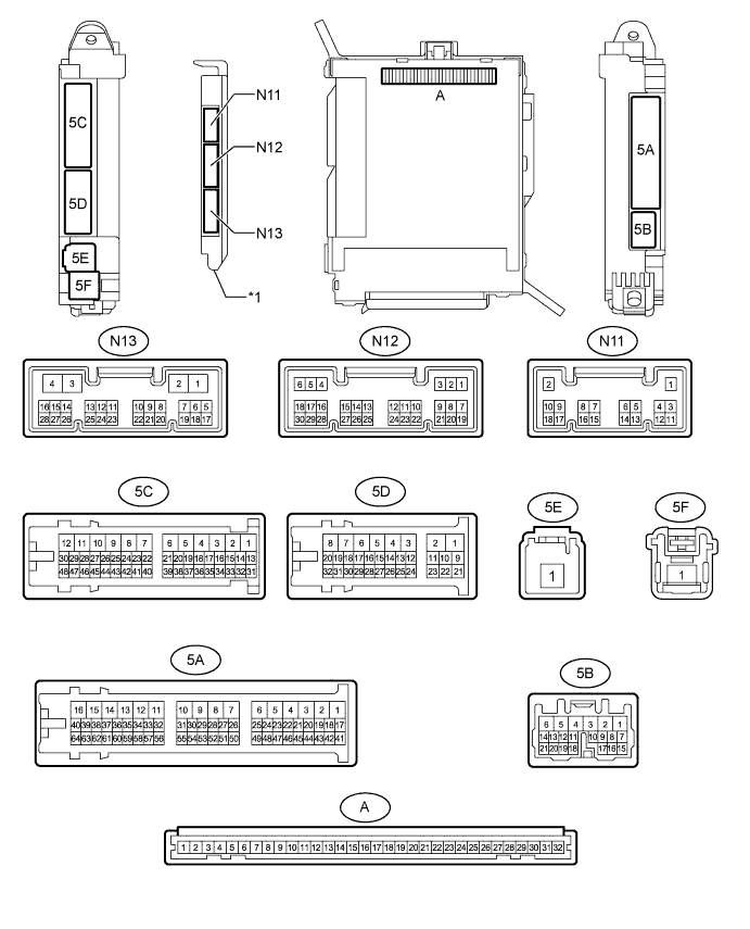
Text in Illustration *1 Main Body ECU (Multiplex Network Body ECU) - -
-
Remove the main body ECU from the cowl side junction block LH Click here.
-
Connect the cowl side junction block LH connectors.
-
Measure the resistance and voltage according to the value(s) in the table below.
Terminal No. (Symbol) Wiring Color Terminal Description Condition Specified Condition A-32 (IG) - Body ground - Ignition power supply Engine switch on (IG) 11 to 14 V A-30 (BECU) - Body ground - Battery power supply Always 11 to 14 V A-29 (ACC) - Body ground - ACC power supply Engine switch on (ACC) 11 to 14 V A-11 (GND1) - Body ground - Ground Always Below 1 Ω -
Install the main body ECU Click here.
-
Measure the voltage according to the value(s) in the table below.
Terminal No. (Symbol) Wiring Color Terminal Description Condition Specified Condition N12-5 (HU) - Body ground P - Body ground Headlight dimmer switch high signal input Headlight dimmer switch in high position Below 1 V Headlight dimmer switch in low position 11 to 14 V N12-8 (HF) - Body ground L - Body ground Headlight dimmer switch high flash signal input Headlight dimmer switch in high flash position Below 1 V Headlight dimmer switch not in high flash position 11 to 14 V N12-28 (A) - Body ground R - Body ground Headlight dimmer switch AUTO signal input Headlight dimmer switch in AUTO position Below 1 V Headlight dimmer switch not in AUTO position 11 to 14 V N12-29 (HEAD) - Body ground LG - Body ground Headlight dimmer switch head signal input Headlight dimmer switch in head position Below 1 V Headlight dimmer switch not in head position 11 to 14 V N12-30 (TAIL) - Body ground B - Body ground Headlight dimmer switch tail signal input Headlight dimmer switch in tail or head position Below 1 V Headlight dimmer switch in neither tail nor head position 11 to 14 V N12-20 (CLTB) - N12-22 (CLTE) GR - W Automatic light control sensor power supply output Engine switch off Below 1 V Engine switch on (IG) and headlight dimmer switch in AUTO position 11 to 14 V N12-21 (CLTS) - Body ground R - Body ground Automatic light control sensor signal input Engine switch off Below 1 V Engine switch on (IG)
Headlight dimmer switch in AUTO position
Automatic light control sensor covered with a hand → Automatic light control sensor exposed to ambient light
Pulse generation
(See waveform)
N12-27 (FFOG) - Body ground*1 B - Body ground Front fog light switch input Front fog light switch on Below 1 V Front fog light switch off 11 to 14 V N13-17 (AHBI) - Body ground*2 Y - Body ground Automatic high beam main switch input Automatic high beam main switch on Below 1 V Automatic high beam main switch off 11 to 14 V N13-23 (RFOG) - Body ground*3 GR - Body ground Rear fog light switch input Rear fog light switch on Below 1 V Rear fog light switch off 11 to 14 V 5D-9 (HRLY) - Body ground Y - Body ground H-LP LO relay drive output Headlight dimmer switch in head position Below 1 V Headlight dimmer switch not in head position 11 to 14 V 5D-11 (TRLY) - Body ground W - Body ground No. 2 integration relay (TAIL relay) drive output Headlight dimmer switch in tail position Below 1 V Headlight dimmer switch not in tail position 11 to 14 V 5D-21 (DIM) - Body ground LG - Body ground No. 2 integration relay (DIMMER relay) drive output Headlight dimmer switch in high or high flash position Below 1 V Headlight dimmer switch not in high or high flash position 11 to 14 V 5D-22 (FFGO) - Body ground*1 GR - Body ground Front fog light signal output Headlight dimmer switch in tail position and front fog light switch on Below 1 V Front fog light switch off 11 to 14 V 5D-23 (DRL) - Body ground G - Body ground No. 2 integration relay (DRL relay) drive output Daytime running light on Below 1 V Daytime running light off 11 to 14 V 5C-16 (RFGO) - Body ground*3 GR - Body ground Rear fog light signal output Headlight dimmer switch in tail position and rear fog light switch on Below 1 V Rear fog light switch off 11 to 14 V 5C-44 (FLCY) - Body ground*4 R - Body ground Front door courtesy light switch LH signal Front door LH open Below 1 V Front door LH closed Pulse generation 5A-33 (FRCY) - Body ground*5 R - Body ground Front door courtesy light switch RH signal Front door RH open Below 1 V Front door RH closed Pulse generation
-
*1: w/ Front Fog Light
-
*2: w/ Automatic High Beam System
-
*3: w/ Rear Fog Light
-
*4: for LHD
-
*5: for RHD
-
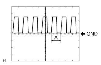
Waveform
Item Content Terminal No. (Symbol) N12-21 (CLTS) - Body ground Tool setting 5 V/DIV., 5 ms./DIV. Condition Engine switch on (IG)
Headlight dimmer switch in AUTO position
Automatic light control sensor covered with a hand → Automatic light control sensor exposed to ambient light
Tech Tips
If the ambient light becomes brighter, width A becomes narrower.
-
-
-
CHECK COMBINATION METER ASSEMBLY
-
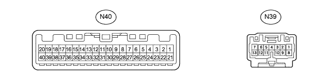
Disconnect the N39 and N40 combination meter connectors.
-
Measure the resistance and voltage according to the value(s) in the table below.
Terminal No. (Symbol) Wiring Color Terminal Description Condition Specified Condition N40-22 (B) - Body ground P - Body ground Battery power supply Always 11 to 14 V N40-21 (IG+) - Body ground B - Body ground Ignition power supply Engine switch off Below 1 V Engine switch on (IG) 11 to 14 V N39-1 (B) - Body ground W - Body ground Battery power supply Always 11 to 14 V N39-11 (HZSW) - Body ground P - Body ground Hazard warning signal switch signal input Hazard warning signal switch on Below 1 Ω Hazard warning signal switch off 10 kΩ or higher N40-30 (ES) - Body ground W-B - Body ground Ground Always Below 1 Ω -
Reconnect the N39 and N40 combination meter connectors.
-
Measure the voltage according to the value(s) in the table below.
Terminal No. (Symbol) Wiring Color Terminal Description Condition Specified Condition N39-9 (ER) - Body ground GR - Body ground Turn signal switch (right turn position) signal input Engine switch on (IG)
Turn signal switch off
11 to 14 V Engine switch on (IG)
Turn signal switch in right turn position
Below 1 V N39-10 (EL) - Body ground G - Body ground Turn signal switch (left turn position) signal input Engine switch on (IG)
Turn signal switch off
11 to 14 V Engine switch on (IG)
Turn signal switch in left turn position
Below 1 V N39-7 (LL) - Body ground Y - Body ground LH turn signal light signal output Engine switch on (IG)
LH turn signal light off
Below 1 V Engine switch on (IG)
LH turn signal light blinking
Below 1 V ←→ 11 to 14 V N39-13 (LR) - Body ground G - Body ground RH turn signal light signal output Engine switch on (IG)
RH turn signal light off
Below 1 V Engine switch on (IG)
RH turn signal light blinking
Below 1 V ←→ 11 to 14 V
-
-
CHECK INNER REAR VIEW MIRROR ASSEMBLY (w/ Automatic High Beam System)

-
Disconnect the Y8 inner rear view mirror connector.
-
Measure the voltage and resistance according to the value(s) in the table below.
Terminal No. (Symbol) Wiring Color Terminal Description Condition Specified Condition Y8-6 (+B) - Body ground R - Body ground Battery power supply Always 11 to 14 V Y8-1 (IG) - Body ground SB - Body ground Ignition power supply Engine switch on (IG) 11 to 14 V Y8-2 (E) - Body ground W-B - Body ground Inner rear view mirror ground Always Below 1 Ω -
Reconnect the Y8 inner rear view mirror connector.
-
Measure the voltage according to the value(s) in the table below.
Terminal No. (Symbol) Wiring Color Terminal Description Condition Specified Condition Y8-10 (LIN) - Body ground R - Body ground LIN communication Automatic high beam system operates Pulse generation
(See waveform)
-
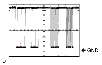
Waveform
Item Content Terminal No. (Symbol) Y8-10 (LIN) - Body ground Tool setting 2 V/DIV., 10 ms./DIV. Condition Automatic high beam system operates
-
-