POWER MIRROR CONTROL SYSTEM Driver Side Power Mirror cannot be Adjusted with Power Mirror Switch
SYSTEM DESCRIPTION
-
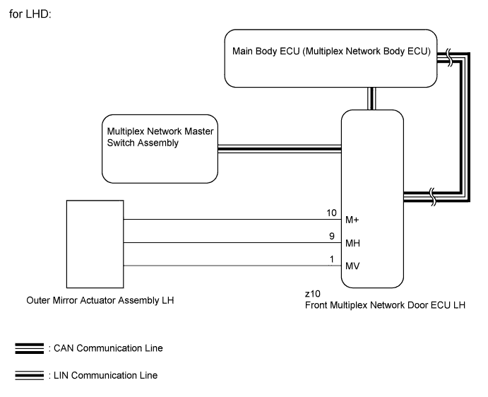
When the mirror operation switch (up/down/left/right for the driver side) of the multiplex network master switch assembly is operated, the left remote mirror selection signal and up/down/left/right signals are sent via LIN communication to the main body ECU (multiplex network body ECU) through the front multiplex network door ECU LH. The main body ECU (multiplex network body ECU) then sends the received signals to the front multiplex door ECU LH via CAN communication. The front multiplex door ECU LH receives the left remote mirror selection signal and up/down/left/right signals and moves the mirror up, down, left and right based on those signals.
for LHD:
-
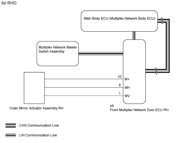
When the mirror operation switch (up/down/left/right for the driver side) of the multiplex network master switch assembly is operated, the right remote mirror selection signal and up/down/left/right signals are sent via LIN communication to the main body ECU (multiplex network body ECU) through the front multiplex network door ECU RH. The main body ECU (multiplex network body ECU) then sends the received signals to the front multiplex door ECU RH via CAN communication. The front multiplex door ECU RH receives the right remote mirror selection signal and up/down/left/right signals and moves the mirror up, down, left and right based on those signals.
for RHD:
WIRING DIAGRAM
INSPECTION PROCEDURE
Note
-
First perform the communication function inspections in How to Proceed with Troubleshooting to confirm that there are no CAN communication malfunctions before troubleshooting this problem.
-
First perform the communication function inspections in How to Proceed with Troubleshooting to confirm that there are no LIN communication malfunctions before troubleshooting this problem.
-
Recognition code registration is necessary when replacing the main body ECU (multiplex network body ECU).
-
If the main body ECU (multiplex network body ECU) is replaced, refer to the Service Bulletin.
PROCEDURE
-
READ VALUE USING GTS (OUTER MIRROR SWITCH)
-
Using the GTS, read the Data List Click here.
Master Switch Tester Display Measurement Item/Range Normal Condition Diagnostic Note Mirror Selection SW (L) Mirror select switch signal for LH mirror / ON or OFF ON: Mirror select switch in L position
OFF: Mirror select switch off or in R position
- Mirror Position SW (L) Mirror adjust switch signal (Left) / ON or OFF ON: Mirror adjust switch pressed left
OFF: Mirror adjust switch not pressed left
Check with the mirror select switch in the R position. Mirror Position SW (R) Mirror adjust switch signal (Right) / ON or OFF ON: Mirror adjust switch pressed right
OFF: Mirror adjust switch not pressed right
Check with the mirror select switch in the R position. Mirror Position SW (Up) Mirror adjust switch signal (Up) / ON or OFF ON: Mirror adjust switch pressed up
OFF: Mirror adjust switch not pressed up
Check with the mirror select switch in the R position. Mirror Position SW (Dwn) Mirror adjust switch signal (Down) / ON or OFF ON: Mirror adjust switch pressed down
OFF: Mirror adjust switch not pressed down
Check with the mirror select switch in the R position. OK The display is as specified in the normal condition column.
NG 
CHECK MULTIPLEX NETWORK MASTER SWITCH ASSEMBLY Click here
OK 
-
-
INSPECT OUTER REAR VIEW MIRROR ASSEMBLY (MIRROR SURFACE FUNCTION)
-
for LHD:
-
Remove the outer rear view mirror assembly LH Click here.
-
Inspect the outer rear view mirror assembly LH Click here.
-
-
for RHD:
-
Remove the outer rear view mirror assembly RH Click here.
-
Inspect the outer rear view mirror assembly RH Click here.
Result Result Proceed to OK (for LHD) A OK (for RHD) B NG (for LHD) C NG (for RHD) D -
B 
REPLACE FRONT MULTIPLEX NETWORK DOOR ECU RH Click here
C
REPLACE OUTER MIRROR ACTUATOR ASSEMBLY LH Click here
D
REPLACE OUTER MIRROR ACTUATOR ASSEMBLY RH Click here
A 
REPLACE FRONT MULTIPLEX NETWORK DOOR ECU LH Click here
-
-
CHECK MULTIPLEX NETWORK MASTER SWITCH ASSEMBLY
-
Temporarily replace multiplex network master switch assembly with a new or normally functioning one Click here.
-
Check that the mirror operates.
OK Mirror operates normally.
NG
REPLACE MAIN BODY ECU (MULTIPLEX NETWORK BODY ECU) Click here
OK
END (MULTIPLEX NETWORK MASTER SWITCH ASSEMBLY IS DEFECTIVE)
-