POWER TRUNK LID SYSTEM TERMINALS OF ECU

-
CHECK COWL SIDE JUNCTION BLOCK LH AND MAIN BODY ECU (MULTIPLEX NETWORK BODY ECU)
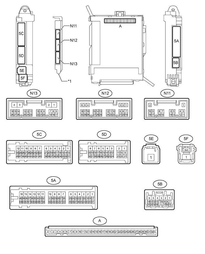
Text in Illustration *1 Main Body ECU (Multiplex Network Body ECU) - -
-
Remove the main body ECU (multiplex network body ECU) from the cowl side junction block LH Click here.
-
Connect the cowl side junction block LH connectors.
-
Measure the voltage and resistance according to the value(s) in the table below.
Terminal No. (Symbol) Wiring Color Terminal Description Condition Specified Condition A-11 (GND1) - Body ground None - Body ground Ground Always Below 1 Ω A-29 (ACC) - Body ground None - Body ground ACC power supply Engine switch on (ACC) 11 to 14 V Engine switch off Below 1 V A-30 (BECU) - Body ground None - Body ground Battery power supply Always 11 to 14 V A-31 (ALTB) - Body ground None - Body ground Battery power supply Always 11 to 14 V A-32 (IG) - Body ground None - Body ground IG power supply Engine switch on (IG) 11 to 14 V Engine switch off Below 1 V -
Install the main body ECU (multiplex network body ECU) to the cowl side junction block LH Click here.
-
Measure the voltage according to the value(s) in the table below.
Terminal No. (Symbol) Wiring Color Terminal Description Condition Specified Condition N13-5 (TMSW) - Body ground G - Body ground Luggage door opening cancel switch input signal Luggage door opening cancel switch is on Below 1 V Engine switch off, all doors closed and luggage door opening cancel switch is off Pulse generation N13-8 (TSW) - Body ground Y - Body ground Luggage door opening switch input signal Luggage door opening switch is on Below 1 V Engine switch off, all doors closed and luggage door opening switch is off Pulse generation N12-23 (TKUL) - Body ground GR - Body ground Luggage compartment door lock cylinder input signal Engine switch off, luggage compartment door lock cylinder operated Below 1 V Engine switch off, luggage compartment door lock cylinder not operated Pulse generation
-
-
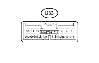
CHECK LUGGAGE CLOSER MOTOR ASSEMBLY
-
Disconnect the U33 luggage closer motor assembly connector.
-
Measure the resistance and voltage according to the value(s) in the table below.
Terminal No. (Symbol) Wiring Color Terminal Description Condition Specified Condition U33-8 (IG) - U33-11 (GND) B - W-B IG power supply Engine switch on (IG) 11 to 14 V U33-10 (ECUB) - U33-11 (GND) P- W-B ECU power supply Always 11 to 14 V U33-11 (GND) - Body ground W-B - Body ground Ground Always Below 1 Ω U33-12 (B) - U33-11 (GND) B - W-B Battery power supply Always 11 to 14 V -
Reconnect the U33 motor connector.
-
Measure the voltage according to the value(s) in the table below.
Terminal No. (Symbol) Wiring Color Terminal Description Condition Specified Condition U33-1 (LCM-) - U33-11 (GND) G - W-B Luggage compartment door closer motor output signal Luggage compartment door closer is operated 11 to 14 V U33-2 (LCM+) - U33-11 (GND) B - W-B Luggage compartment door closer motor output signal Luggage compartment door closer is operated in reverse 11 to 14 V U33-4 (LDDN) - U33-11 (GND) BE - W-B Door control switch input signal Door control switch is on Below 1 V Engine switch on (IG), luggage compartment door closed and door control switch is off Pulse generation U33-7 (HAF) - U33-11 (GND) GR - W-B Luggage compartment door closer half latch switch input signal Engine switch on (IG), luggage compartment door open → fully closed Below 1 V → Pulse generation U33-20 (PAWL) - U33-11 (GND) GR - W-B Luggage compartment door closer pawl switch input signal Engine switch on (IG), luggage compartment door open → fully closed Below 1 V → Pulse generation
-
-
CHECK CERTIFICATION ECU (SMART KEY ECU ASSEMBLY)
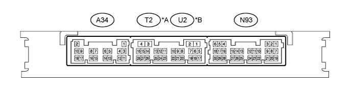
Text in Illustration *A for LHD *B for RHD
-
Disconnect the A34 and N93 certification ECU (smart key ECU assembly) connectors.
-
Measure the resistance and voltage according to the value(s) in the table below.
Terminal No. (Symbol) Wiring Color Terminal Description Condition Specified Condition A34-2 (+B) - Body ground W - Body ground Battery power supply Always 11 to 14 V N93-5 (IG) - Body ground B - Body ground Ignition power supply Engine switch off Below 1 V Engine switch on (IG) 11 to 14 V A34-10 (CUTB) - Body ground P - Body ground Dark current cut fuse pin input signal Always 11 to 14 V A34-11 (E) - Body ground W-B - Body ground*1
BR - Body ground*2
Ground Always Below 1 Ω
-
*1: for LHD
-
*2: for RHD
-
-
Reconnect the A34 and N93 certification ECU (smart key ECU assembly) connectors.
-
Measure the voltage according to the value(s) in the table below.
for LHD Terminal No. (Symbol) Wiring Color Terminal Description Condition Specified Condition T2-27 (TSW5) - A34-11 (E) SB - W-B Luggage electrical key switch input signal Engine switch on (IG), luggage compartment door is fully closed and luggage electrical key switch off Pulse generation for RHD Terminal No. (Symbol) Wiring Color Terminal Description Condition Specified Condition U2-27 (TSW5) - A34-11 (E) SB - BR Luggage electrical key switch input signal Engine switch on (IG), luggage compartment door is fully closed and luggage electrical key switch off Pulse generation
-