LUGGAGE COMPARTMENT DOOR OPENER SYSTEM Luggage Compartment Door Opener does not Operate
DESCRIPTION
The main body ECU (multiplex network body ECU) continuously receives the luggage compartment door opening cancel switch ON/OFF signal. When the luggage compartment door opening cancel switch signal is off, and the luggage compartment door opening switch is on, the luggage closer motor activates the luggage compartment door closer, and opens the luggage compartment door.
WIRING DIAGRAM
Refer to the "System Diagram" Click here.
INSPECTION PROCEDURE
Note
-
If the main body ECU (multiplex network body ECU) or certification ECU (smart key ECU assembly) is replaced, refer to the Service Bulletin.
-
Inspect the fuses for circuits related to this system before performing the following inspection procedure.
PROCEDURE
-
PERFORM ACTIVE TEST USING GTS
-
Select the Active Test, use the GTS to generate a control command, and then check that the luggage closer motor operates Click here.
Back Door (w/ Power Trunk Lid System) Tester Display Test Part Control Range Diagnostic Note Latch Release Operate luggage compartment door latch release ON or OFF - Main Body (w/o Power Trunk Lid System) Tester Display Test Part Control Range Diagnostic Note Trunk and Back-Door Open Operate luggage compartment door latch release ON or OFF - OK Luggage compartment door latch release motor is ON/OFF. Result Result Proceed to OK A NG (w/ Power Trunk Lid System) B NG (w/o Power Trunk Lid System) C
B 
GO TO LUGGAGE COMPARTMENT DOOR CLOSER SYSTEM Click here
C 
CHECK HARNESS AND CONNECTOR (NO. 1 JUNCTION BLOCK - BATTERY) Click here
A 
-
-
READ VALUE USING GTS
-
Using the GTS, read the Data List Click here.
Main Body Tester Display Measurement Item/Range Normal Condition Diagnostic Note Trunk Main SW Luggage door opening cancel switch signal / ON or OFF ON: Luggage door opening cancel switch is on
OFF: Luggage door opening cancel switch is off
- Trunk/BDoor Open SW Luggage door opening switch signal / ON or OFF ON: Luggage door opening switch is on
OFF: Luggage door opening switch is off
- Trunk Lock/Unlock SW Luggage compartment door lock cylinder switch signal / ON or OFF ON: Luggage compartment door lock cylinder on (Luggage compartment door opened)
OFF: Luggage compartment door lock cylinder off (Luggage compartment door closed)
When this item is abnormal, there is a problem with the luggage compartment door lock cylinder switch or related parts. Luggage courtesy SW Luggage door closer courtesy switch signal / ON or OFF ON: Luggage door closer courtesy switch on
OFF: Luggage door closer courtesy switch off
For vehicles with power trunk lid system, this item is not related luggage compartment door condition. OK On GTS screen, each item changes between ON and OFF as shown in above chart. Result Result Proceed to OK A NG (Luggage door opening switch assembly) B NG (Luggage door opening cancel switch assembly) C NG (Luggage compartment door lock cylinder switch assembly) D NG (Luggage courtesy switch) E
B
INSPECT LUGGAGE DOOR OPENING SWITCH ASSEMBLY Click here
C
INSPECT LUGGAGE DOOR OPENING CANCEL SWITCH ASSEMBLY Click here
D
INSPECT LUGGAGE COMPARTMENT DOOR LOCK CYLINDER ASSEMBLY Click here
E
GO TO LIGHTING SYSTEM Click here
A
-
-
READ VALUE USING GTS (TR/B-DOOR UNLOCK SW)
-
Using the GTS, read the Data List Click here.
Entry & Start Tester Display Measurement Item/Range Normal Condition Diagnostic Note Tr/B-Door Unlock SW Luggage electrical key switch / ON or OFF ON: Luggage electrical key switch pushed
OFF: Luggage electrical key switch not pushed
When this item is abnormal, there is a problem with the luggage electrical key switch of the luggage door lock assembly or related parts. OK On GTS screen, each item changes between ON and OFF as shown in above chart.
NG
INSPECT LUGGAGE ELECTRICAL KEY SWITCH Click here
OK
-
-
READ VALUE USING GTS (TRUNK LINK WITH DOOR LOCK)
-
Using the GTS, read the Data List Click here.
Main Body Tester Display Measurement Item/Range Normal Condition Diagnostic Note Trunk Link with Door Lock Luggage compartment door lock function / ON or OFF Customized value displayed - Result Result Proceed to Luggage compartment door lock function is ON (There is a malfunction when only the luggage electrical key switch is operated [all doors are unlocked and the electrical key transmitter sub-assembly is not held]). A Luggage compartment door lock function is OFF (There is a malfunction when only the luggage electrical key switch is operated [electrical key transmitter sub-assembly is held]) (w/ Entry Function). B Luggage compartment door lock function is ON (There is a malfunction when only the luggage electrical key switch is operated [electrical key transmitter sub-assembly is held]) (w/ Entry Function). Luggage compartment door lock function is OFF (There is a malfunction when only the luggage electrical key switch is operated [all doors are unlocked and the electrical key transmitter sub-assembly is not held]). C
B
GO TO ENTRY AND START SYSTEM (for Entry Function) Click here
C
PERFORM CUSTOMIZE SETTING (Proceed to Customize Parameters) Click here
A 
GO TO LIGHTING SYSTEM (Door Unlock Detection Switch Circuit) Click here
-
-
INSPECT LUGGAGE DOOR OPENING SWITCH ASSEMBLY
-
Remove the luggage door opening switch assembly Click here.
-
Inspect the luggage door opening switch assembly Click here.
NG
REPLACE LUGGAGE DOOR OPENING SWITCH ASSEMBLY Click here
OK
-
-
CHECK HARNESS AND CONNECTOR (MAIN BODY ECU - LUGGAGE DOOR OPENING SWITCH AND BODY GROUND)
-
Disconnect the N13 main body ECU connector.
-
Disconnect the N2 luggage door opening switch connector.
-
Measure the resistance according to the value(s) in the table below.
Standard Resistance Tester Connection Condition Specified Condition N13-8 (TSW) - N2-3 (B) Always Below 1 Ω N2-4 (L) - Body ground Always Below 1 Ω N13-8 (TSW) - Body ground Always 10 kΩ or higher
NG
REPAIR OR REPLACE HARNESS OR CONNECTOR
OK
REPLACE MAIN BODY ECU (MULTIPLEX NETWORK BODY ECU) Click here
-
-
INSPECT LUGGAGE DOOR OPENING CANCEL SWITCH ASSEMBLY
-
Remove the luggage door opening cancel switch assembly Click here.
-
Inspect the luggage door opening cancel switch assembly Click here.
NG
REPLACE LUGGAGE DOOR OPENING CANCEL SWITCH ASSEMBLY Click here
OK
-
-
CHECK HARNESS AND CONNECTOR (MAIN BODY ECU - LUGGAGE DOOR OPENING CANCEL SWITCH AND BODY GROUND)
-
Disconnect the N13 main body ECU connector.
-
Disconnect the N84 luggage door opening cancel switch connector.
-
Measure the resistance according to the value(s) in the table below.
Standard Resistance Tester Connection Condition Specified Condition N13-5 (TMSW) - N84-2 Always Below 1 Ω N84-1 - Body ground Always Below 1 Ω N13-5 (TMSW) - Body ground Always 10 kΩ or higher
NG
REPAIR OR REPLACE HARNESS OR CONNECTOR
OK
REPLACE MAIN BODY ECU (MULTIPLEX NETWORK BODY ECU) Click here
-
-
INSPECT LUGGAGE COMPARTMENT DOOR LOCK CYLINDER ASSEMBLY
-
Remove the luggage compartment door lock cylinder assembly Click here.
-
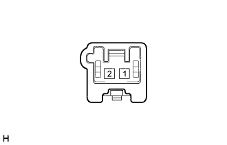
Measure the resistance according to the value(s) in the table below.
Standard Resistance Tester Connection Switch Condition Specified Condition 1 - 2 Not turned 10 kΩ or higher 1 - 2 Open position Below 1 Ω
NG
REPLACE LUGGAGE COMPARTMENT DOOR LOCK CYLINDER ASSEMBLY Click here
OK
-
-
CHECK HARNESS AND CONNECTOR (MAIN BODY ECU - LUGGAGE COMPARTMENT DOOR LOCK CYLINDER AND BODY GROUND)
-
Disconnect the N12 main body ECU connector.
-
Disconnect the a4 luggage compartment door lock cylinder connector.
-
Measure the resistance according to the value(s) in the table below.
Standard Resistance Tester Connection Condition Specified Condition N12-23 (TKUL) - a4-2 Always Below 1 Ω a4-1 - Body ground Always Below 1 Ω N12-23 (TKUL) - Body ground Always 10 kΩ or higher
NG
REPAIR OR REPLACE HARNESS OR CONNECTOR
OK
REPLACE MAIN BODY ECU (MULTIPLEX NETWORK BODY ECU) Click here
-
-
CHECK HARNESS AND CONNECTOR (NO. 1 JUNCTION BLOCK - BATTERY)
-
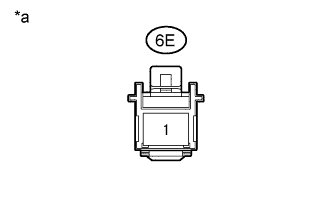
Text in Illustration *a Front view of wire harness connector
(to No. 1 Junction Block Assembly)
Disconnect the No. 1 junction block connector.
-
Measure the voltage according to the value(s) in the table below.
Standard Voltage Tester Connection Condition Specified Condition 6E-1 - Body ground Always 11 to 14 V
NG
REPAIR OR REPLACE HARNESS OR CONNECTOR
OK
-
-
CHECK HARNESS AND CONNECTOR (NO. 1 JUNCTION BLOCK ASSEMBLY - COWL SIDE JUNCTION BLOCK RH)
-
Disconnect the 6A No. 1 junction block connector.
-
Disconnect the 4C cowl side junction block RH connector.
-
Measure the resistance according to the value(s) in the table below.
Standard Resistance Tester Connection Condition Specified Condition 6A-33 - 4C-18 Always Below 1 Ω 6A-33 - Body ground Always 10 kΩ or higher
NG
REPAIR OR REPLACE HARNESS OR CONNECTOR
OK
-
-
CHECK NO. 1 JUNCTION BLOCK ASSEMBLY
-
Temporarily replace the No. 1 junction block with a new or normally functioning one.
-
Check that the luggage door opener system is normal.
OK Luggage door opener system is normal.
NG
CHECK HARNESS AND CONNECTOR (MAIN BODY ECU - COWL SIDE JUNCTION BLOCK RH) Click here
OK
END (NO. 1 JUNCTION BLOCK ASSEMBLY WAS DEFECTIVE)
-
-
CHECK HARNESS AND CONNECTOR (MAIN BODY ECU - COWL SIDE JUNCTION BLOCK RH)
-
Remove the main body ECU (multiplex network body ECU) from the cowl side junction block LH Click here.
-
Disconnect the 4A cowl side junction block RH connector.
-
Measure the resistance according to the value(s) in the table below.
Standard Resistance Tester Connection Condition Specified Condition A-6 (TR+) - 4A-34 Always Below 1 Ω A-6 (TR+) - Body ground Always 10 kΩ or higher
NG
CHECK HARNESS AND CONNECTOR (COWL SIDE JUNCTION BLOCK LH - COWL SIDE JUNCTION BLOCK RH) Click here
OK
-
-
INSPECT LUGGAGE COMPARTMENT DOOR LOCK ASSEMBLY
-
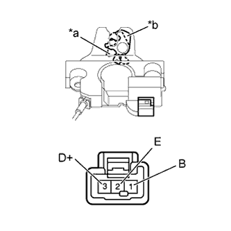
Text in Illustration *a Full latch *b Open latch Remove the luggage compartment door lock assembly Click here.
-
Motor operation check
-
Set the door closer latch to the full latch position.
-
Apply battery voltage to the door closer connector and check the motor operation.
OK Measurement Condition Specified Condition Battery positive (+) → Terminal 1 (B)
Battery negative (-) → Terminal 2 (E)
Luggage compartment door lock full latch → open latch
-
-
Courtesy switch operation check
-
Measure the resistance according to the value(s) in the table below.
Standard Resistance Tester Connection Condition Specified Condition 3 (D+) - 2 (E) Full latch 10 kΩ or higher 3 (D+) - 2 (E) Open latch Below 1 Ω
-
NG
REPLACE LUGGAGE COMPARTMENT DOOR LOCK ASSEMBLY Click here
OK
-
-
CHECK HARNESS AND CONNECTOR (LUGGAGE COMPARTMENT DOOR LOCK - MAIN BODY ECU AND COWL SIDE JUNCTION BLOCK RH AND BODY GROUND)
-
Disconnect the a8 luggage compartment door lock connector.
-
Disconnect the N12 main body ECU connector.
-
Disconnect the 4A and 4D cowl side junction block RH connectors.
-
Measure the resistance according to the value(s) in the table below.
Standard Resistance Tester Connection Condition Specified Condition a8-3 (D+) - N12-19 (LGCY) Always Below 1 Ω a8-1(B) - 4D-18 Always Below 1 Ω 4A-4 - Body ground Always Below 1 Ω a8-2 (E) - Body ground Always Below 1 Ω a8-3 (D+) - Body ground Always 10 kΩ or higher a8-1 (B) - Body ground Always 10 kΩ or higher
NG
REPAIR OR REPLACE HARNESS OR CONNECTOR
OK
-
-
CHECK COWL SIDE JUNCTION BLOCK RH
-
Temporarily replace the cowl side junction block RH with a new or normally functioning one.
-
Check that the luggage door opener system is normal.
OK Luggage door opener system is normal.
NG
REPLACE MAIN BODY ECU (MULTIPLEX NETWORK BODY ECU) Click here
OK
END (COWL SIDE JUNCTION BLOCK RH WAS DEFECTIVE)
-
-
CHECK HARNESS AND CONNECTOR (COWL SIDE JUNCTION BLOCK LH - COWL SIDE JUNCTION BLOCK RH)
-
Disconnect the 5C cowl side junction block LH connector.
-
Disconnect the 4A cowl side junction block RH connector.
-
Measure the resistance according to the value(s) in the table below.
Standard Resistance Tester Connection Condition Specified Condition 5C-17 - 4A-34 Always Below 1 Ω 5C-17 - Body ground Always 10 kΩ or higher
NG
REPAIR OR REPLACE HARNESS OR CONNECTOR
OK
REPLACE COWL SIDE JUNCTION BLOCK LH Click here
-
-
INSPECT LUGGAGE ELECTRICAL KEY SWITCH
-
Remove the luggage electrical key switch Click here.
-
Inspect the luggage electrical key switch Click here.
NG
REPLACE LUGGAGE ELECTRICAL KEY SWITCH
OK
-
-
CHECK HARNESS AND CONNECTOR (LUGGAGE ELECTRICAL KEY - CERTIFICATION ECU [SMART KEY ECU ASSEMBLY] AND BODY GROUND)
-
Disconnect the a7 luggage electrical key switch connector.
-
Disconnect the T2*1 or U2*2 certification ECU (smart key ECU assembly) connector.
-
*1: for LHD
-
*2: for RHD
-
-
Measure the resistance according to the value(s) in the table below.
Standard Resistance for LHD Tester Connection Condition Specified Condition a7-2 - T2-27 (TSW5) Always Below 1 Ω a7-1 - Body ground Always Below 1 Ω a7-2 - Body ground Always 10 kΩ or higher for RHD Tester Connection Condition Specified Condition a7-2 - U2-27 (TSW5) Always Below 1 Ω a7-1 - Body ground Always Below 1 Ω a7-2 - Body ground Always 10 kΩ or higher
NG
REPAIR OR REPLACE HARNESS OR CONNECTOR
OK
REPLACE CERTIFICATION ECU (SMART KEY ECU ASSEMBLY)
-