CLIMATE CONTROL SEAT SYSTEM TERMINALS OF ECU

-
AIR CONDITIONING AMPLIFIER ASSEMBLY
-
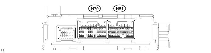
Disconnect the N79 air conditioning amplifier assembly connector.
-
Measure the voltage and resistance according to the value(s) in the table below.
Tech Tips
Measure the values on the wire harness side with the connector disconnected.
Terminal No. (Symbol) Wiring Color Terminal Description Condition Specified Condition N79-6 (+B1) - Body ground W - Body ground Power source (Back-up) Engine switch off 11 to 14 V N79-5 (IG+) - Body ground L - Body ground Power source (IG) Engine switch on (IG) 11 to 14 V N79-1 (GND) - Body ground W-B - Body ground Ground Always Below 1 Ω If the result is not as specified, there may be a malfunction on the wire harness side.
-
Reconnect the N79 air conditioning amplifier assembly connector.
-
Measure the waveform according to the value(s) in the table below.
Terminal No. (Symbol) Wiring Color Terminal Description Condition Specified Condition N79-10 (LOUT) - N79-1 (GND) V - W-B Output climate control signal (for LH side) Engine switch on (IG), refreshing seat switch LH blower on Pulse generation
(See waveform)
N79-11 (ROUT) - N79-1 (GND) L - W-B Output climate control signal (for RH side) Engine switch on (IG), refreshing seat switch RH blower on Pulse generation
(See waveform)
N79-20 (LIN1) - N79-1 (GND) R - W-B LIN communication signal Engine switch on (IG) Pulse generation
-
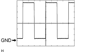
Waveform (Reference): Using an oscilloscope:
Item Content Tester Connection N79-11 (ROUT) - N79-1 (GND)
N79-10 (LOUT) - N79-1 (GND)
Tool Setting 2 V/DIV., 500 μsec/DIV. Vehicle Condition Engine switch on (IG), refreshing seat switch on
-
-
-
CHECK REFRESHING SEAT SWITCH
-
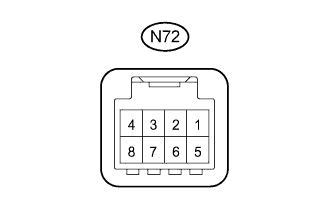
Disconnect the N72 refreshing seat switch connector.
-
Measure the voltage and resistance according to the value(s) in the table below.
Terminal No. (Symbol) Wiring Color Terminal Description Condition Specified Condition N72-7 (IG+) - Body ground LG - Body ground Power source (IG) Engine switch on (IG) 11 to 14 V N72-4 (E) - Body ground W-B - Body ground Ground Always Below 1 Ω If the result is not as specified, there may be a malfunction on the wire harness side.
-
Reconnect the N72 refreshing seat switch connector.
-
Measure the waveform according to the value(s) in the table below.
Terminal No. (Symbol) Wiring Color Terminal Description Condition Specified Condition N72-7 (SW) - N72-4 (E) R - R LIN communication signal Engine switch on (IG) Pulse generation
-