DRIVER MONITOR ECU REMOVAL

Tech Tips
-
Use the same procedure for RHD and LHD vehicles.
-
The procedure listed below is for LHD vehicles.
-
PRECAUTION
Note
After turning the engine switch off, waiting time may be required before disconnecting the cable from the battery terminal. Therefore, make sure to read the disconnecting the cable from the battery terminal notice before proceeding with work Click here.
-
DISCONNECT CABLE FROM NEGATIVE BATTERY TERMINAL
CAUTION:
Wait at least 90 seconds after disconnecting the cable from the negative (-) battery terminal to disable the SRS system.
Note
When disconnecting the cable, some systems need to be initialized after the cable is reconnected Click here.
-
REMOVE INSTRUMENT SIDE PANEL LH (for LHD)
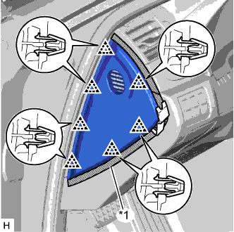
Text in Illustration *1 Protective Tape
-
Put protective tape around the instrument side panel LH.
-
Using a moulding remover, detach the 7 clips and remove the instrument side panel LH.
-
-
REMOVE INSTRUMENT SIDE PANEL RH (for RHD)
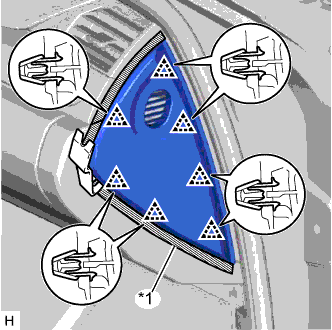
Text in Illustration *1 Protective Tape
-
Put protective tape around the instrument side panel RH.
-
Using a moulding remover, detach the 7 clips and remove the instrument side panel RH.
-
w/ Airbag Cut Off Switch:
-
Disconnect the connector.
-
-
-
REMOVE NO. 1 INSTRUMENT PANEL GARNISH SUB-ASSEMBLY
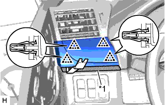
Text in Illustration *1 Protective Tape
-
Put protective tape around the No. 1 instrument panel garnish sub-assembly.
-
Using a moulding remover, detach the 4 clips and remove the No. 1 instrument panel garnish sub-assembly.
-
-
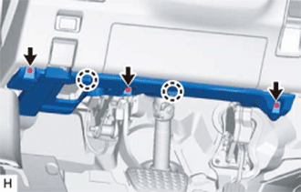
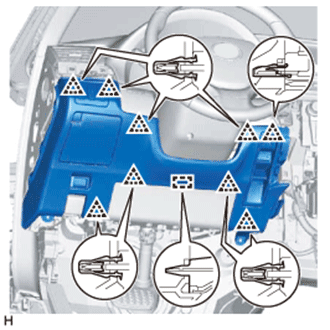
REMOVE NO. 1 INSTRUMENT PANEL UNDER COVER SUB-ASSEMBLY
-
Remove the 3 screws <A>.
-
Detach the 2 claws.
-
Disconnect the connectors, detach the clamp and remove the No. 1 instrument panel under cover sub-assembly.
-
-
REMOVE CENTER INSTRUMENT CLUSTER FINISH PANEL
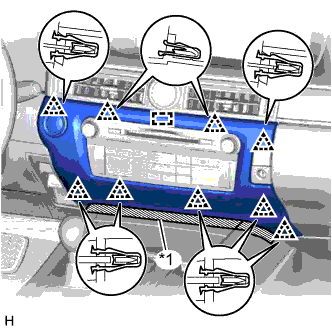
Text in Illustration *1 Protective Tape
-
Put protective tape around the center instrument cluster finish panel.
-
Detach the 9 clips and guide.
-
Disconnect the connector and remove the center instrument cluster finish panel.
-
-
REMOVE INSTRUMENT PANEL FINISH PANEL END LH (for LHD)
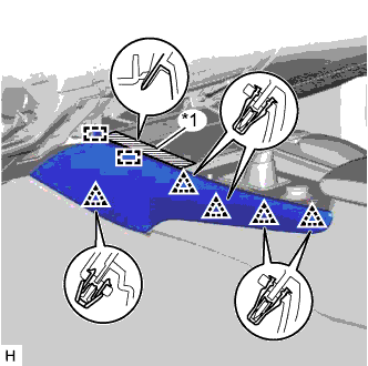
Text in Illustration *1 Protective Tape
-
Put protective tape around the instrument panel finish panel end LH.
-
Detach the 5 clips and 2 guides and remove the instrument panel finish panel end LH.
-
-
REMOVE INSTRUMENT PANEL FINISH PANEL END RH (for RHD)
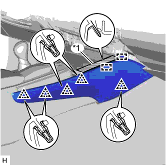
Text in Illustration *1 Protective Tape
-
Put protective tape around the instrument panel finish panel end RH.
-
Detach the 5 clips and 2 guides and remove the instrument panel finish panel end RH.
-
-
REMOVE NO. 1 INSTRUMENT PANEL SAFETY PAD SUB-ASSEMBLY
-
Detach the 9 clips and guide.
-
Disconnect the connectors and remove the No. 1 instrument panel safety pad sub-assembly.
-
-
REMOVE LOWER NO. 1 INSTRUMENT PANEL AIRBAG ASSEMBLY
CAUTION:
When storing the lower No. 1 instrument panel airbag assembly, keep the airbag deployment side facing upward.
-
Check that the engine switch is off.
-
Check that the cable is disconnected from the negative (-) battery terminal.
CAUTION:
Wait at least 90 seconds after disconnecting the cable from the negative (-) battery terminal to disable the SRS system.
-
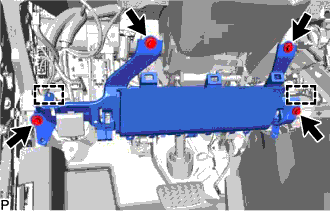
Remove the 4 bolts.
-
Detach the hook and pin to separate the lower No. 1 instrument panel airbag assembly.
Note
When separating the lower No. 1 instrument panel airbag assembly, do not pull the airbag wire harness.
-
Detach the 3 claws to disconnect the hood lock control lever sub-assembly from the lower No. 1 instrument panel airbag assembly.
-
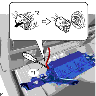
Using a screwdriver with the tip wrapped with protective tape, release the airbag connector lock.
-
Disconnect the airbag connector to remove the lower No. 1 instrument panel airbag assembly.
Text in Illustration *1 Protective Tape *2 Connector Lock Note
When disconnecting any airbag connector, take care not to damage the airbag wire harness.
-
-
REMOVE NO. 2 AIR DUCT SUB-ASSEMBLY (for RHD)
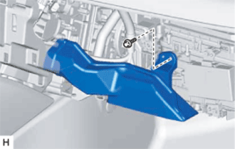
-
Remove the screw and No. 2 air duct sub-assembly.
-
-
REMOVE DRIVER MONITOR ECU ASSEMBLY
-
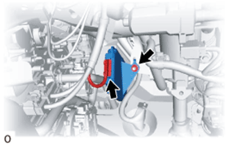
Disconnect the connector.
-
Remove the nut and driver monitor ECU assembly.
-