CLOCK INSPECTION

Tech Tips
-
Use the same procedure for RHD and LHD vehicles.
-
The procedure listed below is for LHD vehicles.
-
INSPECT CLOCK ASSEMBLY
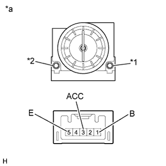
Text in Illustration *1 Knob A *2 Knob B *a Component without harness connected
(Clock Assembly)
-
Apply battery voltage to the connector and check the operation.
OK Measurement Condition Switch Condition Specified Condition Battery positive (+) → Terminal 1 (B)
Battery negative (-) → Terminal 5 (E)
Knob A on
(Pushed)
Long hand rotates clockwise Knob B on
(Pushed)
Long hand rotates counterclockwise Battery positive (+) → Terminal 3 (ACC)
Battery negative (-) → Terminal 5 (E)
Knob A on
(Pushed)
Long hand rotates clockwise Knob B on
(Pushed)
Long hand rotates counterclockwise If the result is not as specified, replace the clock assembly.
-
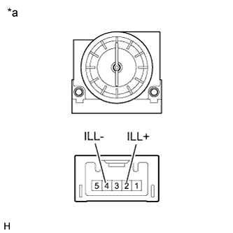
Text in Illustration *a Component without harness connected
(Clock Assembly)
Apply battery voltage to the connector and check the illumination condition.
OK Measurement Condition Specified Condition Battery positive (+) → Terminal 2 (ILL+)
Battery negative (-) → Terminal 4 (ILL-)
Illuminates If the result is not as specified, replace the clock assembly.
-