METER / GAUGE SYSTEM Vehicle Speed Signal Circuit
DESCRIPTION
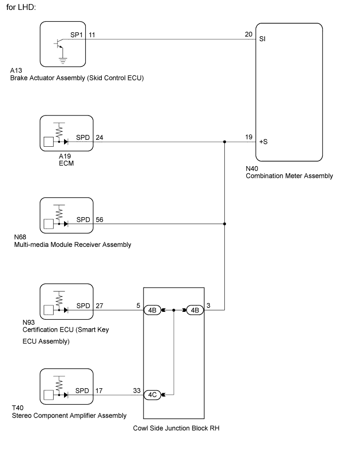
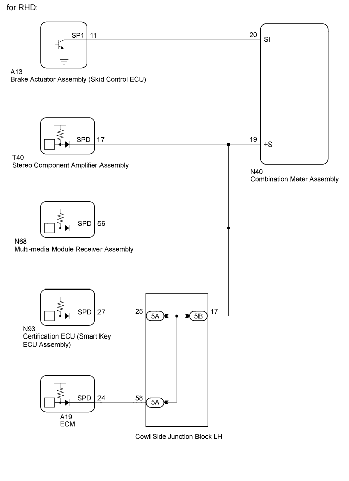
The vehicle speed signal consists of pulses sent to the combination meter assembly from the brake actuator assembly (skid control ECU).
WIRING DIAGRAM
INSPECTION PROCEDURE
Note
Before replacing the certification ECU (smart key ECU assembly), refer to the Service Bulletin.
PROCEDURE
-
CONFIRM MODEL
Result Result Proceed to for LHD A for RHD B
B 
CHECK STEREO COMPONENT AMPLIFIER ASSEMBLY Click here
A 
-
CHECK ECM
-
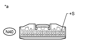
Text in Illustration *a Front view of wire harness connector
(to Combination Meter Assembly)
Disconnect the N40 combination meter assembly connector.
-
Disconnect the N68 multi-media module receiver assembly connector.
-
Disconnect the 4B junction block connector.
-
Measure the voltage according to the value(s) in the table below.
Standard Voltage Tester Connection Switch Condition Specified Condition N40-19 (+S) - Body ground Engine switch on (IG) 4.5 to 14 V
NG
CHECK HARNESS AND CONNECTOR (COMBINATION METER ASSEMBLY - ECM) Click here
OK
-
-
CHECK MULTI-MEDIA MODULE RECEIVER ASSEMBLY
-
Text in Illustration *a Front view of wire harness connector
(to Combination Meter Assembly)
Disconnect the N40 combination meter assembly connector.
-
Disconnect the A19 ECM connector.
-
Disconnect the 4B junction block connector.
-
Measure the voltage according to the value(s) in the table below.
Standard Voltage Tester Connection Switch Condition Specified Condition N40-19 (+S) - Body ground Engine switch on (IG) 4.5 to 14 V
NG
CHECK HARNESS AND CONNECTOR (COMBINATION METER ASSEMBLY - MULTI-MEDIA MODULE RECEIVER ASSEMBLY) Click here
OK
-
-
CHECK CERTIFICATION ECU (SMART KEY ECU ASSEMBLY)
-
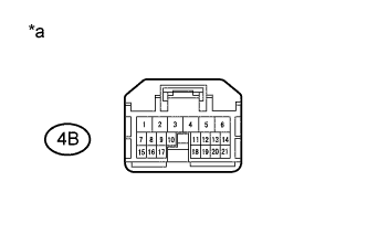
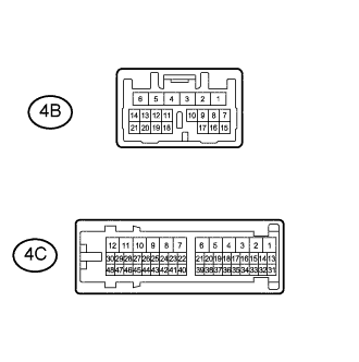
Text in Illustration *a Front view of wire harness connector
(to Cowl Side Junction Block RH)
Disconnect the 4B junction block connector.
-
Measure the voltage according to the value(s) in the table below.
Standard Voltage Tester Connection Switch Condition Specified Condition 4B-5 - Body ground Engine switch on (IG) 4.5 to 14 V
NG
CHECK HARNESS AND CONNECTOR (COWL SIDE JUNCTION BLOCK RH - CERTIFICATION ECU [SMART KEY ECU ASSEMBLY]) Click here
OK
-
-
CHECK STEREO COMPONENT AMPLIFIER ASSEMBLY
-
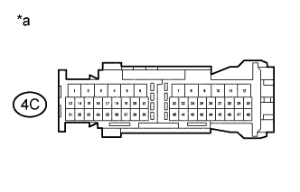
Text in Illustration *a Front view of wire harness connector
(to Cowl Side Junction Block RH)
Disconnect the 4C junction block connector.
-
Measure the voltage according to the value(s) in the table below.
Standard Voltage Tester Connection Switch Condition Specified Condition 4C-33 - Body ground Engine switch on (IG) 4.5 to 14 V
NG
CHECK HARNESS AND CONNECTOR (COWL SIDE JUNCTION BLOCK RH - STEREO COMPONENT AMPLIFIER ASSEMBLY) Click here
OK
-
-
CHECK HARNESS AND CONNECTOR (COMBINATION METER ASSEMBLY - COWL SIDE JUNCTION BLOCK RH)
-
Disconnect the N40 combination meter assembly connector.
-
Disconnect the 4B junction block connector.
-
Disconnect the A19 ECM connector.
-
Disconnect the N68 multi-media module receiver assembly connector.
-
Measure the resistance according to the value(s) in the table below.
Standard Resistance Tester Connection Condition Specified Condition N40-19 (+S) - 4B-3 Always Below 1 Ω N40-19 (+S) - Body ground Always 10 kΩ or higher
NG 
REPAIR OR REPLACE HARNESS OR CONNECTOR
OK
-
-
INSPECT COWL SIDE JUNCTION BLOCK RH
-
Remove the cowl side junction block RH.
-
Measure the resistance according to the value(s) in the table below.
Standard Resistance Tester Connection Condition Specified Condition 4B-3 - 4B-5 Always Below 1 Ω 4B-3 - 4C-33
NG
REPLACE COWL SIDE JUNCTION BLOCK RH
OK
-
-
CHECK COMBINATION METER ASSEMBLY
-
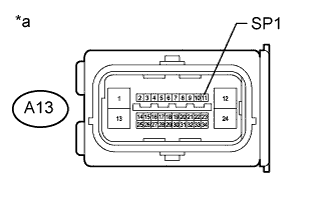
Text in Illustration *a Front view of wire harness connector
(to Brake Actuator Assembly [Skid Control ECU])
Disconnect the A13 brake actuator assembly (skid control ECU) connector.
-
Measure the voltage according to the value(s) in the table below.
Standard Voltage Tester Connection Switch Condition Specified Condition A13-11 (SP1) - Body ground Engine switch on (IG) 11 to 14 V
NG
CHECK HARNESS AND CONNECTOR (COMBINATION METER ASSEMBLY - BRAKE ACTUATOR ASSEMBLY) Click here
OK
-
-
CHECK COMBINATION METER ASSEMBLY
-
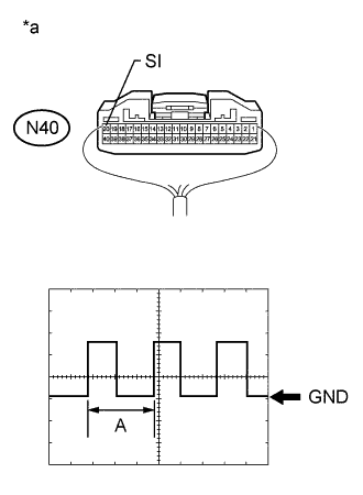
Text in Illustration *a Component with harness connected
(Combination Meter Assembly)
Remove the combination meter assembly with the connector(s) connected.
-
Connect an oscilloscope to terminal N40-20 (SI) and body ground.
-
Check the signal waveform according to the condition(s) in the table below.
Measurement Condition Item Condition Tester connection N40-20 (SI) - Body ground Tool setting 5 V/DIV., 20 ms/DIV. Vehicle condition Driving at approx. 20 km/h (12 mph) OK The waveform displayed is as shown in the illustration. Tech Tips
When the system is functioning normally, one wheel revolution generates 4 pulses. As the vehicle speed increases, the width indicated by (A) in the illustration narrows.
NG
REPLACE BRAKE ACTUATOR ASSEMBLY Click here
OK 
REPLACE COMBINATION METER ASSEMBLY Click here
-
-
CHECK HARNESS AND CONNECTOR (COMBINATION METER ASSEMBLY - ECM)
-
Disconnect the N40 combination meter assembly connector.
-
Disconnect the A19 ECM connector.
-
Disconnect the N68 multi-media module receiver connector.
-
Disconnect the 4B junction block connector.
-
Measure the resistance according to the value(s) in the table below.
Standard Resistance Tester Connection Condition Specified Condition N40-19 - A19-24 (SPD) Always Below 1 Ω N40-19 - Body ground Always 10 kΩ or higher Result Result Proceed to OK (2GR-FSE) A OK (4GR-FSE) B NG C
B
REPLACE ECM Click here
C
REPAIR OR REPLACE HARNESS OR CONNECTOR
A
REPLACE ECM Click here
-
-
CHECK HARNESS AND CONNECTOR (COMBINATION METER ASSEMBLY - MULTI-MEDIA MODULE RECEIVER ASSEMBLY)
-
Disconnect the N40 combination meter assembly connector.
-
Disconnect the N68 multi-media module receiver assembly connector.
-
Disconnect the A19 ECM connector.
-
Disconnect the 4B junction block connector.
-
Measure the resistance according to the value(s) in the table below.
Standard Resistance Tester Connection Condition Specified Condition N40-19 - N68-56 (SPD) Always Below 1 Ω N40-19 - Body ground Always 10 kΩ or higher
NG
REPAIR OR REPLACE HARNESS OR CONNECTOR
OK
REPLACE MULTI-MEDIA MODULE RECEIVER ASSEMBLY Click here
-
-
CHECK HARNESS AND CONNECTOR (COWL SIDE JUNCTION BLOCK RH - CERTIFICATION ECU [SMART KEY ECU ASSEMBLY])
-
Disconnect the 4B junction block connector.
-
Disconnect the N93 certification ECU connector.
-
Measure the resistance according to the value(s) in the table below.
Standard Resistance Tester Connection Condition Specified Condition 4B-5 - N93-27 (SPD) Always Below 1 Ω 4B-5 - Body ground Always 10 kΩ or higher
NG
REPAIR OR REPLACE HARNESS OR CONNECTOR
OK
REPLACE CERTIFICATION ECU (SMART KEY ECU ASSEMBLY)
-
-
CHECK HARNESS AND CONNECTOR (COWL SIDE JUNCTION BLOCK RH - STEREO COMPONENT AMPLIFIER ASSEMBLY)
-
Disconnect the 4C junction block connector.
-
Disconnect the T40 stereo component amplifier assembly connector.
-
Measure the resistance according to the value(s) in the table below.
Standard Resistance Tester Connection Condition Specified Condition 4C-33 - T40-17 (SPD) Always Below 1 Ω 4C-33 - Body ground Always 10 kΩ or higher
NG
REPAIR OR REPLACE HARNESS OR CONNECTOR
OK
REPLACE STEREO COMPONENT AMPLIFIER ASSEMBLY Click here
-
-
CHECK STEREO COMPONENT AMPLIFIER ASSEMBLY
-
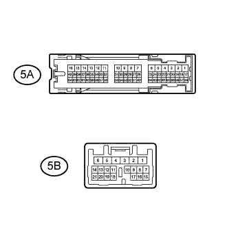
Text in Illustration *a Front view of wire harness connector
(to Combination Meter Assembly)
Disconnect the N40 combination meter assembly connector.
-
Disconnect the N68 multi-media module receiver assembly connector.
-
Disconnect the 5B junction block connector.
-
Measure the voltage according to the value(s) in the table below.
Standard Voltage Tester Connection Switch Condition Specified Condition N40-19 (+S) - Body ground Engine switch on (IG) 4.5 to 14 V
NG
CHECK HARNESS AND CONNECTOR (COMBINATION METER ASSEMBLY - STEREO COMPONENT AMPLIFIER ASSEMBLY) Click here
OK
-
-
CHECK MULTI-MEDIA MODULE RECEIVER ASSEMBLY
-
Text in Illustration *a Front view of wire harness connector
(to Combination Meter Assembly)
Disconnect the N40 combination meter assembly connector.
-
Disconnect the T40 stereo component amplifier assembly connector.
-
Disconnect the 5B junction block connector.
-
Measure the voltage according to the value(s) in the table below.
Standard Voltage Tester Connection Switch Condition Specified Condition N40-19 (+S) - Body ground Engine switch on (IG) 4.5 to 14 V
NG
CHECK HARNESS AND CONNECTOR (COMBINATION METER ASSEMBLY - MULTI-MEDIA MODULE RECEIVER ASSEMBLY) Click here
OK
-
-
CHECK CERTIFICATION ECU (SMART KEY ECU ASSEMBLY)
-
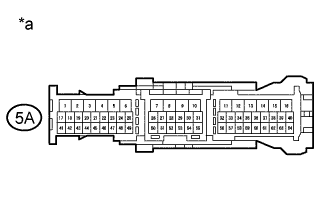
Text in Illustration *a Front view of wire harness connector
(to Cowl Side Junction Block LH)
Disconnect the 5A junction block connector.
-
Measure the voltage according to the value(s) in the table below.
Standard Voltage Tester Connection Switch Condition Specified Condition 5A-25 - Body ground Engine switch on (IG) 4.5 to 14 V
NG
CHECK HARNESS AND CONNECTOR (COWL SIDE JUNCTION BLOCK LH - CERTIFICATION ECU [SMART KEY ECU ASSEMBLY]) Click here
OK
-
-
CHECK ECM
-
Text in Illustration *a Front view of wire harness connector
(to Cowl Side Junction Block LH)
Disconnect the 5A junction block connector.
-
Measure the voltage according to the value(s) in the table below.
Standard Voltage Tester Connection Switch Condition Specified Condition 5A-25 - Body ground Engine switch on (IG) 4.5 to 14 V
NG
CHECK HARNESS AND CONNECTOR (COWL SIDE JUNCTION BLOCK LH - ECM) Click here
OK
-
-
CHECK HARNESS AND CONNECTOR (COMBINATION METER ASSEMBLY - COWL SIDE JUNCTION BLOCK LH)
-
Disconnect the N40 combination meter assembly connector.
-
Disconnect the 5B junction block connector.
-
Disconnect the T40 stereo component amplifier assembly connector.
-
Disconnect the N68 multi-media module receiver assembly connector.
-
Measure the resistance according to the value(s) in the table below.
Standard Resistance Tester Connection Condition Specified Condition N40-19 (+S) - 5B-17 Always Below 1 Ω N40-19 (+S) - Body ground Always 10 kΩ or higher
NG
REPAIR OR REPLACE HARNESS OR CONNECTOR
OK
-
-
INSPECT COWL SIDE JUNCTION BLOCK LH
-
Remove the cowl side junction block LH.
-
Measure the resistance according to the value(s) in the table below.
Standard Resistance Tester Connection Condition Specified Condition 5B-17 - 5A-25 Always Below 1 Ω 5B-17 - 5A-58
NG
REPLACE COWL SIDE JUNCTION BLOCK LH
OK
-
-
CHECK COMBINATION METER ASSEMBLY
-
Text in Illustration *a Front view of wire harness connector
(to Brake Actuator Assembly [Skid Control ECU])
Disconnect the A13 brake actuator assembly (skid control ECU) connector.
-
Measure the voltage according to the value(s) in the table below.
Standard Voltage Tester Connection Switch Condition Specified Condition A13-11 (SP1) - Body ground Engine switch on (IG) 11 to 14 V
NG
CHECK HARNESS AND CONNECTOR (COMBINATION METER ASSEMBLY - BRAKE ACTUATOR ASSEMBLY) Click here
OK
-
-
CHECK COMBINATION METER ASSEMBLY
-
Text in Illustration *a Component with harness connected
(Combination Meter Assembly)
Remove the combination meter assembly with the connector(s) connected.
-
Connect an oscilloscope to terminal N40-20 (SI) and body ground.
-
Check the signal waveform according to the condition(s) in the table below.
Measurement Condition Item Condition Tester connection N40-20 (SI) - Body ground Tool setting 5 V/DIV., 20 ms/DIV. Vehicle condition Driving at approx. 20 km/h (12 mph) OK The waveform displayed is as shown in the illustration. Tech Tips
When the system is functioning normally, one wheel revolution generates 4 pulses. As the vehicle speed increases, the width indicated by (A) in the illustration narrows.
NG
REPLACE BRAKE ACTUATOR ASSEMBLY Click here
OK
REPLACE COMBINATION METER ASSEMBLY Click here
-
-
CHECK HARNESS AND CONNECTOR (COMBINATION METER ASSEMBLY - STEREO COMPONENT AMPLIFIER ASSEMBLY)
-
Disconnect the N40 combination meter assembly connector.
-
Disconnect the T40 stereo component amplifier assembly connector.
-
Disconnect the N68 multi-media module receiver assembly connector.
-
Disconnect the 5B junction block connector.
-
Measure the resistance according to the value(s) in the table below.
Standard Resistance Tester Connection Condition Specified Condition N40-19 - T40-17 (SPD) Always Below 1 Ω N40-19 - Body ground Always 10 kΩ or higher
NG
REPAIR OR REPLACE HARNESS OR CONNECTOR
OK
REPLACE STEREO COMPONENT AMPLIFIER ASSEMBLY Click here
-
-
CHECK HARNESS AND CONNECTOR (COMBINATION METER ASSEMBLY - MULTI-MEDIA MODULE RECEIVER ASSEMBLY)
-
Disconnect the N40 combination meter assembly connector.
-
Disconnect the N68 multi-media module receiver assembly connector.
-
Disconnect the T40 stereo component amplifier assembly connector.
-
Disconnect the 5B junction block connector.
-
Measure the resistance according to the value(s) in the table below.
Standard Resistance Tester Connection Condition Specified Condition N40-19 - N68-56 (SPD) Always Below 1 Ω N40-19 - Body ground Always 10 kΩ or higher
NG
REPAIR OR REPLACE HARNESS OR CONNECTOR
OK
REPLACE MULTI-MEDIA MODULE RECEIVER ASSEMBLY Click here
-
-
CHECK HARNESS AND CONNECTOR (COWL SIDE JUNCTION BLOCK LH - CERTIFICATION ECU [SMART KEY ECU ASSEMBLY])
-
Disconnect the 5A junction block connector.
-
Disconnect the N93 certification ECU (smart key ECU assembly) connector.
-
Measure the resistance according to the value(s) in the table below.
Standard Resistance Tester Connection Condition Specified Condition 5A-25 - N93-27 (SPD) Always Below 1 Ω 5A-25 - Body ground Always 10 kΩ or higher
NG
REPAIR OR REPLACE HARNESS OR CONNECTOR
OK
REPLACE CERTIFICATION ECU (SMART KEY ECU ASSEMBLY)
-
-
CHECK HARNESS AND CONNECTOR (COWL SIDE JUNCTION BLOCK LH - ECM)
-
Disconnect the 5A junction block connector.
-
Disconnect the A19 ECM connector.
-
Measure the resistance according to the value(s) in the table below.
Standard Resistance Tester Connection Condition Specified Condition 5A-58 - A19-24 (SPD) Always Below 1 Ω 5A-58 - Body ground Always 10 kΩ or higher Result Result Proceed to OK (2GR-FSE) A OK (4GR-FSE) B NG C
B
REPLACE ECM Click here
C
REPAIR OR REPLACE HARNESS OR CONNECTOR
A
REPLACE ECM Click here
-
-
CHECK HARNESS AND CONNECTOR (COMBINATION METER ASSEMBLY - BRAKE ACTUATOR ASSEMBLY)
-
Disconnect the N40 combination meter assembly connector.
-
Disconnect the A13 brake actuator assembly (skid control ECU) connector.
-
Measure the resistance according to the value(s) in the table below.
Standard Resistance Tester Connection Condition Specified Condition N40-20 (SI) - A13-11 (SP1) Always Below 1 Ω N40-20 (SI) - Body ground Always 10 kΩ or higher
NG
REPAIR OR REPLACE HARNESS OR CONNECTOR
OK
REPLACE COMBINATION METER ASSEMBLY Click here
-