METER / GAUGE SYSTEM, Diagnostic DTC:B1500

| DTC Code | DTC Name |
|---|---|
| B1500 | Fuel Sender Open Detected |
DESCRIPTION
This DTC is stored when the combination meter detects a fuel sender gauge malfunction.
| DTC Code | DTC Detection Condition | Trouble Area |
|---|---|---|
| B1500 | Both conditions are met:
|
|
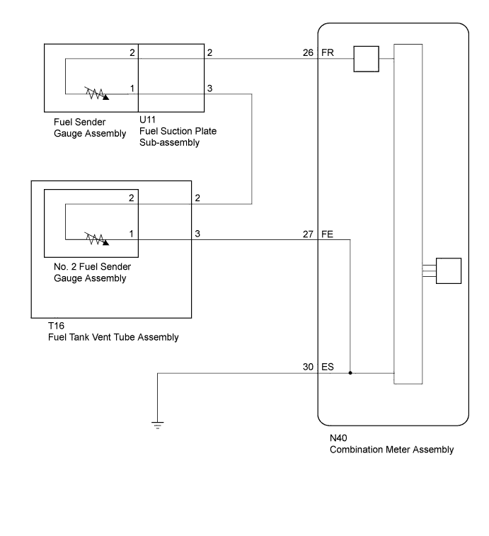
WIRING DIAGRAM
INSPECTION PROCEDURE
PROCEDURE
-
READ VALUE USING GTS (FUEL INPUT)
-
Operate the GTS according to the display and select the Data List Click here.
Combination Meter Tester Display Measurement Item/Range Normal Condition Diagnostic Note Fuel Input Fuel input signal/Min.: 0, Max. 127.5 Current fuel level displayed Unit: Liters. OK Fuel amount value displayed on the GTS is almost the same as needle indication.
NG 
CHECK HARNESS AND CONNECTOR (COMBINATION METER ASSEMBLY - FUEL SUCTION PLATE SUB-ASSEMBLY, FUEL TANK VENT TUBE ASSEMBLY AND BODY GROUND) Click here
OK 
REPLACE COMBINATION METER ASSEMBLY Click here
-
-
CHECK HARNESS AND CONNECTOR (COMBINATION METER ASSEMBLY - FUEL SUCTION PLATE SUB-ASSEMBLY, FUEL TANK VENT TUBE ASSEMBLY AND BODY GROUND)
-
Disconnect the N40 combination meter assembly connector.
-
Disconnect the U11 fuel suction plate sub-assembly connector.
-
Disconnect the T16 fuel tank vent tube assembly connector.
-
Measure the resistance according to the value(s) in the table below.
Standard Resistance Tester Connection Condition Specified Condition N40-26 (FR) - U11-2 Always Below 1 Ω N40-27 (FE) - T16-3 U11-3 - T16-2 N40-30 (ES) - Body ground N40-26 (FR) - Body ground Always 10 kΩ or higher N40-27 (FE) - Body ground U11-3 - Body ground
NG 
REPAIR OR REPLACE HARNESS OR CONNECTOR
OK 
-
-
INSPECT FUEL SENDER GAUGE ASSEMBLY
-
2GR-FSE:
-
Remove the fuel sender gauge assembly Click here [w/ Canister Pump Module], Click here [w/o Canister Pump Module]).
-
Inspect the fuel sender gauge assembly Click here [w/ Canister Pump Module], Click here [w/o Canister Pump Module]).
-
-
4GR-FSE:
-
Remove the fuel sender gauge assembly Click here [w/ Canister Pump Module], Click here [w/o Canister Pump Module]).
-
Inspect the fuel sender gauge assembly Click here [w/ Canister Pump Module], Click here [w/o Canister Pump Module]).
Result Result Proceed to OK A NG (2GR-FSE [w/ Canister Pump Module]) B NG (2GR-FSE [w/o Canister Pump Module]) C NG (4GR-FSE [w/ Canister Pump Module]) D NG (4GR-FSE [w/o Canister Pump Module]) E -
B
REPLACE FUEL SENDER GAUGE ASSEMBLY Click here
C
REPLACE FUEL SENDER GAUGE ASSEMBLY Click here
D
REPLACE FUEL SENDER GAUGE ASSEMBLY Click here
E
REPLACE FUEL SENDER GAUGE ASSEMBLY Click here
A
-
-
INSPECT FUEL SUCTION PLATE SUB-ASSEMBLY
-
2GR-FSE:
-
Remove the fuel suction plate sub-assembly Click here [w/ Canister Pump Module], Click here [w/o Canister Pump Module]).
-
-
4GR-FSE:
-
Remove the fuel suction plate sub-assembly Click here [w/ Canister Pump Module], Click here [w/o Canister Pump Module]).
-
-
Measure the resistance according to the value(s) in the table below.
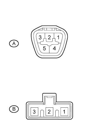
Standard Resistance Tester Connection Condition Specified Condition A-2 - B-2 Always Below 1 Ω A-3 - B-1 Result Result Proceed to OK A NG (2GR-FSE [w/ Canister Pump Module]) B NG (2GR-FSE [w/o Canister Pump Module]) C NG (4GR-FSE [w/ Canister Pump Module]) D NG (4GR-FSE [w/o Canister Pump Module]) E
B
REPLACE FUEL SUCTION PLATE SUB-ASSEMBLY Click here
C
REPLACE FUEL SUCTION PLATE SUB-ASSEMBLY Click here
D
REPLACE FUEL SUCTION PLATE SUB-ASSEMBLY Click here
E
REPLACE FUEL SUCTION PLATE SUB-ASSEMBLY Click here
A
-
-
INSPECT NO. 2 FUEL SENDER GAUGE ASSEMBLY
-
2GR-FSE:
-
Remove the No. 2 fuel sender gauge assembly Click here [w/ Canister Pump Module], Click here [w/o Canister Pump Module]).
-
Inspect the No. 2 fuel sender gauge assembly Click here [w/ Canister Pump Module], Click here [w/o Canister Pump Module]).
-
-
4GR-FSE:
-
Remove the No. 2 fuel sender gauge assembly Click here [w/ Canister Pump Module], Click here [w/o Canister Pump Module]).
-
Inspect the No. 2 fuel sender gauge assembly Click here [w/ Canister Pump Module], Click here [w/o Canister Pump Module]).
Result Result Proceed to OK A NG (2GR-FSE [w/ Canister Pump Module]) B NG (2GR-FSE [w/o Canister Pump Module]) C NG (4GR-FSE [w/ Canister Pump Module]) D NG (4GR-FSE [w/o Canister Pump Module]) E -
B
REPLACE NO. 2 FUEL SENDER GAUGE ASSEMBLY Click here
C
REPLACE NO. 2 FUEL SENDER GAUGE ASSEMBLY Click here
D
REPLACE NO. 2 FUEL SENDER GAUGE ASSEMBLY Click here
E
REPLACE NO. 2 FUEL SENDER GAUGE ASSEMBLY Click here
A
-
-
INSPECT FUEL TANK VENT TUBE ASSEMBLY
-
2GR-FSE:
-
Remove the fuel tank vent tube assembly Click here [w/ Canister Pump Module], Click here [w/o Canister Pump Module]).
-
-
4GR-FSE:
-
Remove the fuel tank vent tube assembly Click here [w/ Canister Pump Module], Click here [w/o Canister Pump Module]).
-
-
Measure the resistance according to the value(s) in the table below.
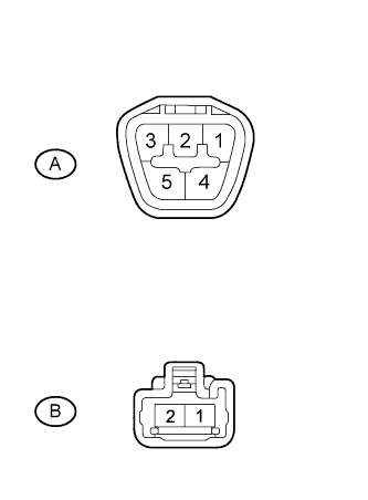
Standard Resistance Tester Connection Condition Specified Condition A-2 - B-2 Always Below 1 Ω A-3 - B-1 Result Result Proceed to OK A NG (2GR-FSE [w/ Canister Pump Module]) B NG (2GR-FSE [w/o Canister Pump Module]) C NG (4GR-FSE [w/ Canister Pump Module]) D NG (4GR-FSE [w/o Canister Pump Module]) E
B
REPLACE FUEL TANK VENT TUBE ASSEMBLY Click here
C
REPLACE FUEL TANK VENT TUBE ASSEMBLY Click here
D
REPLACE FUEL TANK VENT TUBE ASSEMBLY Click here
E
REPLACE FUEL TANK VENT TUBE ASSEMBLY Click here
A
REPLACE COMBINATION METER ASSEMBLY Click here
-