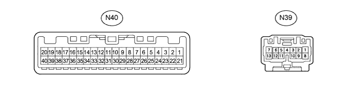
METER / GAUGE SYSTEM TERMINALS OF ECU

-
COMBINATION METER ASSEMBLY
-
Measure the voltage and resistance according to the value(s) in the table below.
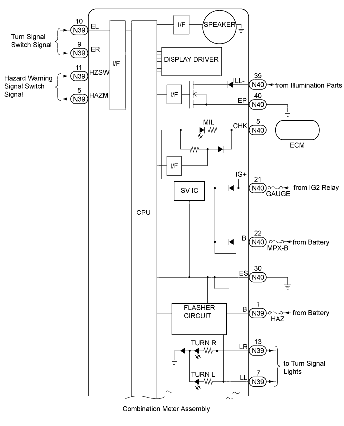
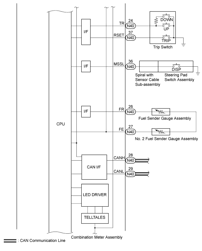
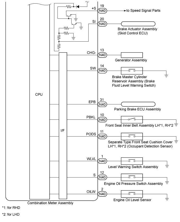
Terminal No. (Symbol) Wiring Color Terminal Description Condition Specified Condition N40-1 (WLVL) - Body ground GR - Body ground Washer fluid level warning switch signal Engine switch on (IG), washer fluid level warning display off 11 to 14 V Engine switch on (IG), washer fluid level warning display on Below 1 V N40-2 (OILW) - Body ground R - Body ground Engine oil level sensor signal Engine switch on (IG), engine oil level warning display off 11 to 14 V Engine switch on (IG), engine oil level warning display on Below 1 V N40-5 (CHK) - Body ground B - Body ground MIL (Malfunction Indicator Light) signal Engine switch on (IG), MIL (Malfunction Indicator Light) off 11 to 14 V Engine switch on (IG), MIL (Malfunction Indicator Light) on 0 to 4.2 V N40-10 (PBKL) - Body ground P - Body ground Front passenger side seat belt buckle switch signal Engine switch on (IG), front passenger side seat belt fastened 11 to 14 V Engine switch on (IG), front passenger side seat belt unfastened Below 1 V N40-11 (PODS) - Body ground W - Body ground Front passenger seat condition signal Engine switch on (IG), sitting on front passenger seat 11 to 14 V Engine switch on (IG), not sitting on front passenger seat Below 1 V N40-12 (S) - Body ground Y - Body ground Engine oil pressure switch signal Engine switch on (IG), engine oil pressure warning display off 11 to 14 V Engine switch on (IG), engine oil pressure warning display on Below 1 V N40-13 (CHG-) - Body ground B - Body ground Charge warning light signal Engine switch on (IG), charge warning light off 11 to 14 V Engine switch on (IG), charge warning light on Below 1 V N40-14 (SW) - Body ground Y - Body ground Brake fluid level warning switch signal Engine switch on (IG), brake fluid level warning switch off 11 to 14 V Engine switch on (IG), brake fluid level warning switch on Below 1 V N40-19 (+S) - Body ground SB - Body ground Speed signal for other systems (Output) Driving at approximately 20 km/ h (12 mph) Pulse generation (See waveform 1) N40-20 (SI) - Body ground V - Body ground Speed signal for other systems (Input) Driving at approximately 20 km/ h (12 mph) Pulse generation (See waveform 1) N40-21 (IG+) - Body ground B - Body ground Engine switch signal (IG) Engine switch off Below 1 V Engine switch on (IG) 11 to 14 V N40-22 (B) - Body ground P - Body ground Battery Always 11 to 14 V N40-24 (TR) - Body ground GR - Body ground Light control rheostat signal Light control rheostat up switch off 4.6 to 5.3 V Light control rheostat up switch on Below 1 V Light control rheostat down switch off 4.6 to 5.3 V Light control rheostat down switch on 2 to 3.6 V N40-26 (FR) - Body ground BR - Body ground Fuel level signal Fuel level F Below 1 V Fuel level E 4.5 to 9 V N40-27 (FE) - Body ground W - Body ground Ground (Fuel ground) Always Below 1 Ω N40-30 (ES) - Body ground W-B - Body ground Ground (Signal ground) Always Below 1 Ω N40-31 (EPB) - Body ground GR - Body ground Parking brake switch signal Engine switch on (IG), parking brake switch off 11 to 14 V Engine switch on (IG), parking brake switch on Below 1.5 V N40-33 (TX+) - Body ground* GR - Body ground Headup display communication signal Engine switch on (IG) Pulse generation (See waveform 2) N40-34 (CS) - Body ground* L - Body ground Headup display communication signal Engine switch on (IG) Pulse generation (See waveform 3) N40-36 (MSSL) - Body ground L - Body ground Steering pad switch (DISP) signal Steering pad switch (DISP) off 11 to 14 V Steering pad switch (DISP) on Below 1 V N40-37 (RSET) - Body ground G - Body ground ODO/TRIP switch signal ODO/TRIP switch off 11 to 14 V ODO/TRIP switch on Below 1 V N40-39 (ILL-) - Body ground W - Body ground Headlight dimmer switch (TAIL) signal Engine switch on (IG), headlight dimmer switch (TAIL) off 11 to 14 V Engine switch on (IG), headlight dimmer switch (TAIL) on Below 1 V N40-40 (EP) - Body ground W-B - Body ground Ground (Illumination ground) Always Below 1 Ω
-
*: w/ Headup Display
-
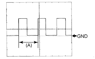
Using an oscilloscope, check waveform 1.
Waveform 1 (Reference) Item Condition Tester connection N40-19 (+S) - Body ground
N40-20 (SI) - Body ground
Tool setting 5 V/DIV., 20 ms./DIV. Vehicle condition Driving at approx. 20 km/h (12 mph) Tech Tips
When the system is functioning normally, one wheel revolution generates 4 pulses. As the vehicle speed increases, the width indicated by (A) in the illustration narrows.
-
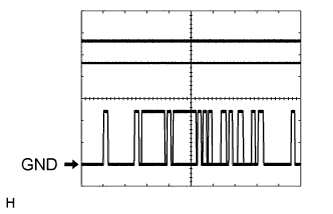
Using an oscilloscope, check waveform 2.
Waveform 2 (Reference) Item Condition Tester connection N40-33 (TX+) - Body ground Tool setting 5 V/DIV., 200 μs./DIV. Vehicle condition Engine switch on (IG) Tech Tips
The period of the signal changes depending on the communication state.
-
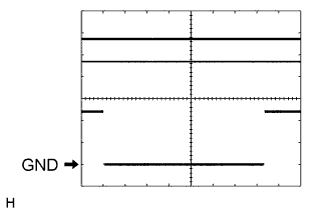
Using an oscilloscope, check waveform 3.
Waveform 3 (Reference) Item Condition Tester connection N40-34 (CS) - Body ground Tool setting 5 V/DIV., 2 ms./DIV. Vehicle condition Engine switch on (IG) Tech Tips
The period of the signal changes depending on the communication state.
-
-
-
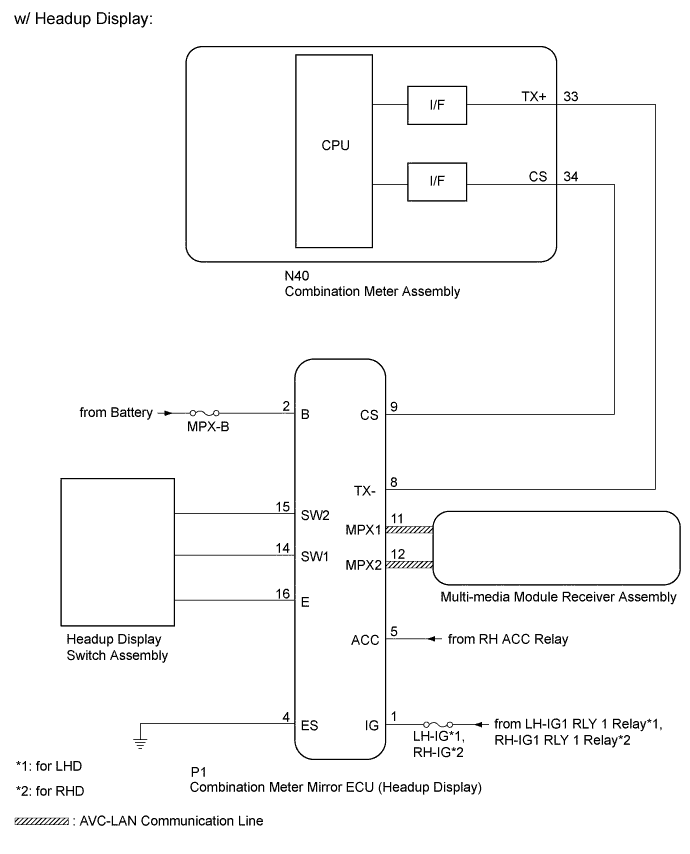
COMBINATION METER MIRROR ECU (HEADUP DISPLAY) (w/ Headup Display)

-
Measure the voltage and resistance according to the value(s) in the table below.
Terminal No. (Symbol) Wiring Color Terminal Description Condition Specified Condition P1-1 (IG) - Body ground L - Body ground Engine switch signal Engine switch on (IG) 11 to 14 V Engine switch off Below 1 V P1-2 (B) - Body ground P - Body ground Battery Always 11 to 14 V P1-4 (ES) - Body ground W-B - Body ground Ground Always Below 1 Ω P1-5 (ACC) - Body ground GR - Body ground Engine switch signal Engine switch on (ACC) 11 to 14 V Engine switch off 0 to 4.2 V P1-8 (TX-) - Body ground GR - Body ground Combination meter communication signal Engine switch on (IG) Pulse generation (See waveform 1) P1-9 (CS) - Body ground L - Body ground Combination meter communication signal Engine switch on (IG) Pulse generation (See waveform 2) P1-11 (MPX1) - Body ground P - Body ground Multi-media module receiver communication signal Engine switch on (IG) Pulse generation P1-12 (MPX2) - Body ground R - Body ground Multi-media module receiver communication signal Engine switch on (IG) Pulse generation P1-14 (SW1) - Body ground G - Body ground Headup display switch signal Headup display switch (HUD) off 4.7 to 5.5 V Headup display switch (HUD) on 0 to 0.6 V Headup display switch (DISP) off 4.7 to 5.5 V Headup display switch (DISP) on 0.8 to 1.6 V P1-15 (SW2) - Body ground Y - Body ground Headup display switch signal Headup display switch (contrast up) off 4.7 to 5.5 V Headup display switch (contrast up) on 0.8 to 1.6 V Headup display switch (contrast down) off 4.7 to 5.5 V Headup display switch (contrast down) on 0 to 0.6 V Headup display switch (position up) off 4.7 to 5.5 V Headup display switch (position up) on 3.1 to 4.1 V Headup display switch (position down) off 4.7 to 5.5 V Headup display switch (position down) on 1.8 to 2.7 V P1-16 (E) - Body ground B - Body ground Ground (Illumination ground) Always Below 1 Ω
-
Using an oscilloscope, check waveform 1.
Waveform 1 (Reference) Item Condition Tester connection P1-8 (TX-) - Body ground Tool setting 5 V/DIV., 200 μs./DIV. Vehicle condition Engine switch on (IG) Tech Tips
The period of the signal changes depending on the communication state.
-
Using an oscilloscope, check waveform 2.
Waveform 2 (Reference) Item Condition Tester connection P1-9 (CS) - Body ground Tool setting 5 V/DIV., 2 ms./DIV. Vehicle condition Engine switch on (IG) Tech Tips
The period of the signal changes depending on the communication state.
-
-
-
COMBINATION METER ASSEMBLY INNER CIRCUIT