ROOM LIGHT (for Front) INSPECTION

-
INSPECT MAP LIGHT ASSEMBLY
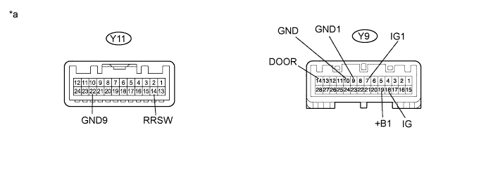
Text in Illustration *a Component without harness connected
(Map Light Assembly)
- -
-
Measure the resistance according to the value(s) in the table below.
Standard Resistance Tester Connection Switch Condition Specified Condition Y9-19 (+B1) - Y11-22 (GND9) Dome light switch off 10 kΩ or higher Dome light switch on Below 1 Ω Spot light switch RH off 10 kΩ or higher Spot light switch RH on Below 1 Ω Spot light switch LH off 10 kΩ or higher Spot light switch LH on Below 1 Ω Y11-14 (RRSW) - Y9-14 (DOOR) Not door position 10 kΩ or higher Door position Below 1 Ω Y9-7 (IG1) - Y9-18 (IG) Always Below 1 Ω Y9-9 (GND1) - Y9-10 (GND) Always Below 1 Ω If the result is not as specified, replace the map light assembly.
-
Apply battery voltage to the connector and check the light illumination condition.
OK Measurement Condition Specified Condition Battery positive (+) → Terminal Y9-19 (+B1)
Battery negative (-) → Terminal Y11-22 (GND9)
Dome light switch on the illuminates Battery positive (+) → Terminal Y9-19 (+B1)
Battery negative (-) → Terminal Y11-22 (GND9)
Spot light switch RH on the illuminates Battery positive (+) → Terminal Y9-19 (+B1)
Battery negative (-) → Terminal Y11-22 (GND9)
Spot light switch LH on the illuminates If the result is not as specified, replace the map light assembly.
-