LIGHTING SYSTEM Illumination Circuit
DESCRIPTION
The main body ECU and front multiplex network door ECU controls the interior illumination lights.
WIRING DIAGRAM
INSPECTION PROCEDURE
Note
-
First perform the communication function inspections in How to Proceed with Troubleshooting to confirm that there are no CAN communication malfunctions before troubleshooting this DTC.
-
Inspect the fuses for circuits related to this system before performing the following inspection procedure.
-
Recognition code registration is necessary when replacing the main body ECU (multiplex network body ECU).
-
If the main body ECU (multiplex network body ECU) is replaced, refer to the Service Bulletin.
PROCEDURE
-
CHECK OPERATION
-
Check the operation of each light.
Result Result Proceed to Front door illumination does not illuminates A Rear door illumination and interior foot light do not illuminates B
B 
PERFORM ACTIVE TEST USING GTS (ILLUMINATION LIGHT) Click here
A 
-
-
PERFORM ACTIVE TEST USING GTS (ILLUMINATION LIGHT)
-
Using the GTS, perform the Active Test Click here.
Front Left Door Tester Display Test Part Control Range Diagnostic Note Inside Handle Light Front door inside handle illumination light LH ON/OFF - Interior Illumination Light Front door ambient light LH ON/OFF - Front Right Door Tester Display Test Part Control Range Diagnostic Note Inside Handle Light Front door inside handle illumination light RH ON/OFF - Interior Illumination Light Front door ambient light RH ON/OFF - OK Front door inside handle illumination light and front door ambient light illuminates. Result Result Proceed to OK A NG (Front door inside handle illumination light does not illuminates) B NG (No. 1 interior illumination light [front door ambient light] does not illuminates) C
B
INSPECT FRONT DOOR INSIDE HANDLE ILLUMINATION LIGHT ASSEMBLY Click here
C
INSPECT NO. 1 INTERIOR ILLUMINATION LIGHT (FRONT DOOR AMBIENT LIGHT) Click here
A 
PROCEED TO NEXT SUSPECTED AREA SHOWN IN PROBLEM SYMPTOMS TABLE Click here
-
-
INSPECT FRONT DOOR INSIDE HANDLE ILLUMINATION LIGHT ASSEMBLY
-
Remove the front door inside handle illumination light Click here.
-
Inspect the front door inside handle illumination light Click here.
NG 
REPLACE FRONT DOOR INSIDE HANDLE ILLUMINATION LIGHT ASSEMBLY Click here
OK
-
-
CHECK HARNESS AND CONNECTOR (FRONT MULTIPLEX NETWORK DOOR ECU - FRONT DOOR INSIDE HANDLE ILLUMINATION LIGHT)
-
for LH:
-
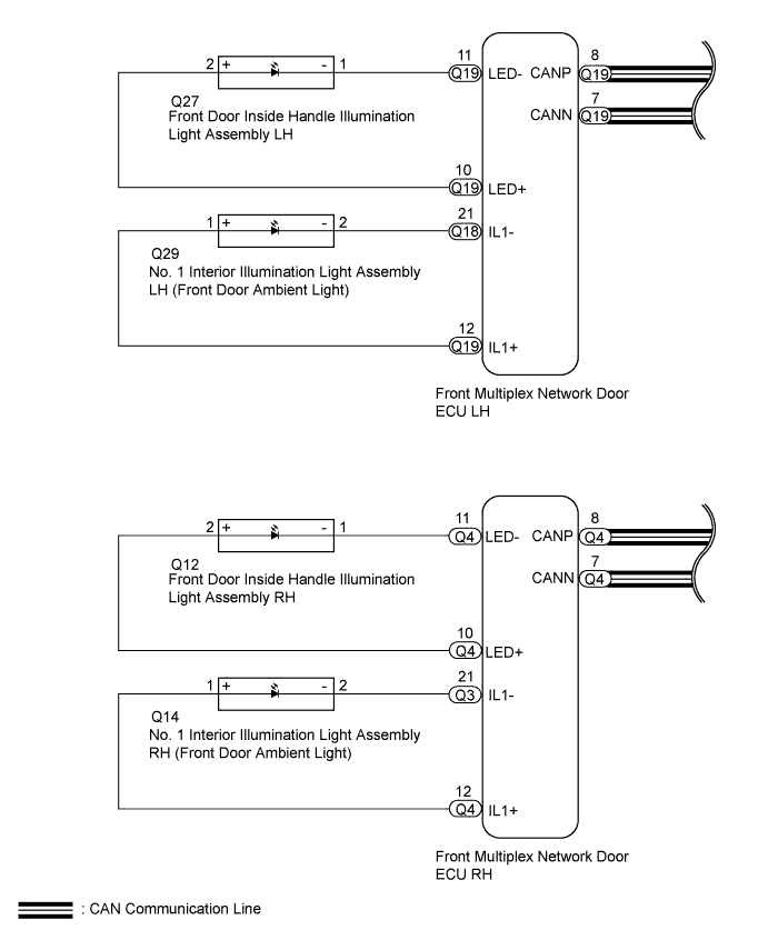
Disconnect the Q19 front multiplex network door ECU LH connector.
-
Disconnect the Q27 front door inside handle illumination light LH connector.
-
-
for RH:
-
Disconnect the Q4 front multiplex network door ECU RH connector.
-
Disconnect the Q12 front door inside handle illumination light RH connector.
-
-
Measure the resistance according to the value(s) in the table below.
Standard Resistance for LH Tester Connection Condition Specified Condition Q19-11 (LED-) - Q27-1 (-) Always Below 1 Ω Q19-10 (LED+) - Q27-2 (+) Always Below 1 Ω Q19-11 (LED-) - Body ground Always 10 kΩ or higher Q19-10 (LED+) - Body ground Always 10 kΩ or higher for RH Tester Connection Condition Specified Condition Q4-11 (LED-) - Q12-1 (-) Always Below 1 Ω Q4-10 (LED+) - Q12-2 (+) Always Below 1 Ω Q4-11 (LED-) - Body ground Always 10 kΩ or higher Q4-10 (LED+) - Body ground Always 10 kΩ or higher
NG
REPAIR OR REPLACE HARNESS OR CONNECTOR
OK
REPLACE FRONT MULTIPLEX NETWORK DOOR ECU Click here
-
-
INSPECT NO. 1 INTERIOR ILLUMINATION LIGHT (FRONT DOOR AMBIENT LIGHT)
-
Remove the No. 1 interior illumination light (front door ambient light) Click here.
-
Inspect the No. 1 interior illumination light (front door ambient light) Click here.
NG
REPLACE NO. 1 INTERIOR ILLUMINATION LIGHT (FRONT DOOR AMBIENT LIGHT) Click here
OK
-
-
CHECK HARNESS AND CONNECTOR (FRONT MULTIPLEX NETWORK DOOR ECU - NO. 1 INTERIOR ILLUMINATION LIGHT [FRONT DOOR AMBIENT LIGHT])
-
for LH:
-
Disconnect the Q18 and Q19 front multiplex network door ECU LH connectors.
-
Disconnect the Q29 No. 1 interior illumination light LH (front door ambient light) connector.
-
-
for RH:
-
Disconnect the Q3 and Q4 front multiplex network door ECU RH connectors.
-
Disconnect the Q14 No. 1 interior illumination light RH (front door ambient light) connector.
-
-
Measure the resistance according to the value(s) in the table below.
Standard Resistance for LH Tester Connection Condition Specified Condition Q18-21 (IL1-) - Q29-2 (-) Always Below 1 Ω Q19-12 (IL1+) - Q29-1 (+) Always Below 1 Ω Q18-21 (IL1-) - Body ground Always 10 kΩ or higher Q19-12 (IL1+) - Body ground Always 10 kΩ or higher for RH Tester Connection Condition Specified Condition Q3-21 (IL1-) - Q14-2 (-) Always Below 1 Ω Q4-12 (IL1+) - Q14-1 (+) Always Below 1 Ω Q3-21 (IL1-) - Body ground Always 10 kΩ or higher Q4-12 (IL1+) - Body ground Always 10 kΩ or higher
NG
REPAIR OR REPLACE HARNESS OR CONNECTOR
OK
REPLACE FRONT MULTIPLEX NETWORK DOOR ECU Click here
-
-
PERFORM ACTIVE TEST USING GTS (ILLUMINATION LIGHT)
-
Using the GTS, perform the Active Test Click here.
Main Body Tester Display Test Part Control Range Diagnostic Note Fr Foot Light Rear door inside handle illumination light, rear door ambient light, rear interior foot light and front interior foot light ON/OFF - OK Rear door inside handle illumination light, rear door ambient light, rear interior foot light and front interior foot light illuminates.
NG
CHECK HARNESS AND CONNECTOR (REAR DOOR INSIDE HANDLE ILLUMINATION LIGHT - MAIN BODY ECU AND BODY GROUND) Click here
OK
PROCEED TO NEXT SUSPECTED AREA SHOWN IN PROBLEM SYMPTOMS TABLE Click here
-
-
CHECK HARNESS AND CONNECTOR (REAR DOOR INSIDE HANDLE ILLUMINATION LIGHT - MAIN BODY ECU AND BODY GROUND)
-
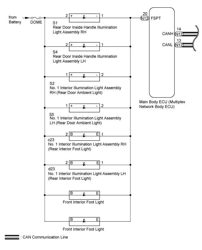
Disconnect the N13 main body ECU connector.
-
Disconnect the S4 rear door inside handle illumination light connector.
-
Measure the voltage according to the value(s) in the table below.
Standard Voltage Tester Connection Condition Specified Condition S4-2 (+) - Body ground Always 11 to 14 V -
Measure the resistance according to the value(s) in the table below.
Standard Resistance Tester Connection Condition Specified Condition S4-1 (-) - N13-20 (FSPT) Always Below 1 Ω S4-1 (-) - Body ground Always 10 kΩ or higher
NG
REPAIR OR REPLACE HARNESS OR CONNECTOR
OK
REPLACE MAIN BODY ECU (MULTIPLEX NETWORK BODY ECU) Click here
-