LIGHTING SYSTEM ACC Signal Circuit
DESCRIPTION
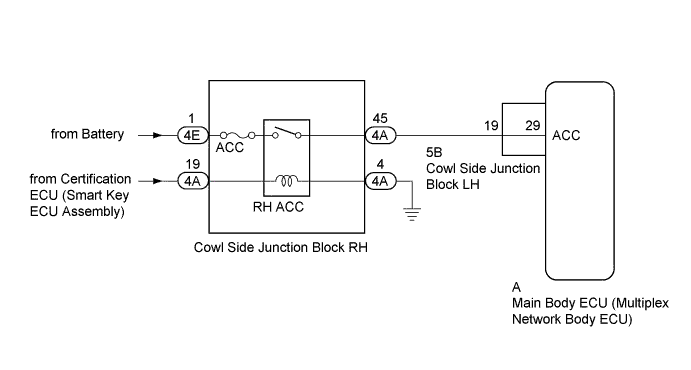
This circuit detects whether the engine switch is on (ACC) or off, and sends this information to the main body ECU.
WIRING DIAGRAM
INSPECTION PROCEDURE
Note
-
Inspect the fuses for circuits related to this system before performing the following inspection procedure.
-
Recognition code registration is necessary when replacing the main body ECU (multiplex network body ECU).
-
If the main body ECU (multiplex network body ECU) is replaced, refer to the Service Bulletin.
PROCEDURE
-
READ VALUE USING GTS (ACC SW)
-
Using the GTS, read the Data List Click here.
Main Body Tester Display Measurement Item/Range Normal Condition Diagnostic Note ACC SW Engine switch on (ACC) signal / ON or OFF ON: Engine switch on (ACC)
OFF: Engine switch off
"ON" is also displayed for this item when the engine switch is on (IG). OK The display is as specified in the normal condition column.
NG 
CHECK HARNESS AND CONNECTOR (COWL SIDE JUNCTION BLOCK RH - BATTERY AND BODY GROUND) Click here
OK 
PROCEED TO NEXT SUSPECTED AREA SHOWN IN PROBLEM SYMPTOMS TABLE Click here
-
-
CHECK HARNESS AND CONNECTOR (COWL SIDE JUNCTION BLOCK RH - BATTERY AND BODY GROUND)
-
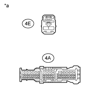
Text in Illustration *a Front view of wire harness connector
(to Cowl Side Junction Block RH)
Disconnect the cowl side junction block RH connectors.
-
Measure the voltage according to the value(s) in the table below.
Standard Voltage Tester Connection Condition Specified Condition 4E-1 - Body ground Always 11 to 14 V 4A-19 - Body ground Engine switch on (ACC) 11 to 14 V -
Measure the resistance according to the value(s) in the table below.
Standard Resistance Tester Connection Condition Specified Condition 4A-4 - Body ground Always Below 1 Ω
NG 
REPAIR OR REPLACE HARNESS OR CONNECTOR
OK 
-
-
INSPECT COWL SIDE JUNCTION BLOCK RH (RH ACC RELAY)
-
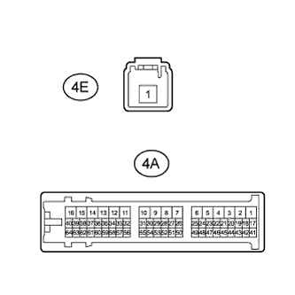
Remove the cowl side junction block RH.
-
Measure the resistance according to the value(s) in the table below.
Standard Resistance Tester Connection Condition Specified Condition 4E-1 - 4A-45 Battery voltage not applied between terminals 4A-19 and 4A-4 10 kΩ or higher Battery voltage applied between terminals 4A-19 and 4A-4 Below 1 Ω
NG
REPLACE COWL SIDE JUNCTION BLOCK RH
OK
-
-
CHECK HARNESS AND CONNECTOR (COWL SIDE JUNCTION BLOCK RH - COWL SIDE JUNCTION BLOCK LH)
-
Disconnect the 4A cowl side junction block RH connector.
-
Disconnect the 5B cowl side junction block LH connector.
-
Measure the resistance according to the value(s) in the table below.
Standard Resistance Tester Connection Condition Specified Condition 4A-45 - 5B-19 Always Below 1 Ω 4A-45 - Body ground Always 10 kΩ or higher
NG
REPAIR OR REPLACE HARNESS OR CONNECTOR
OK
-
-
INSPECT COWL SIDE JUNCTION BLOCK LH
-
Remove the cowl side junction block LH Click here.
-
Remove the main body ECU from the cowl side junction block LH Click here.
-
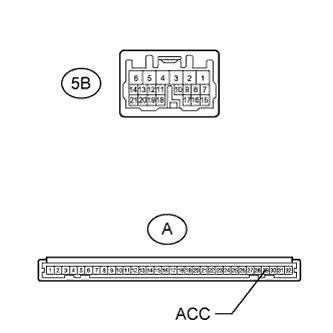
Measure the resistance according to the value(s) in the table below.
Standard Resistance Tester Connection Condition Specified Condition 5B-19 - A-29 (ACC) Always Below 1 Ω
NG
REPLACE COWL SIDE JUNCTION BLOCK LH Click here
OK
REPLACE MAIN BODY ECU (MULTIPLEX NETWORK BODY ECU) Click here
-