ENTRY AND START SYSTEM (for Entry Function), Diagnostic DTC:B27A8

| DTC Code | DTC Name |
|---|---|
| B27A8 | Open in Outside Luggage Compartment Electrical Key Antenna Circuit |
DESCRIPTION
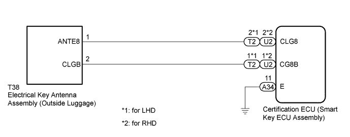
The certification ECU (smart key ECU assembly) generates a request signal and transmits the signal to the electrical key antenna (outside luggage). For the electrical key antenna (outside luggage) to detect when the electrical key transmitter sub-assembly is brought close to the vehicle, the received request signal is transmitted within approximately 1.0 m (3.28 ft.) of the luggage compartment door. DTC B27A8 is stored by the certification ECU (smart key ECU assembly) when an open circuit is detected between the certification ECU (smart key ECU assembly) and electrical key antenna (outside luggage) (between terminals CLG8 and ANTE8, or terminals CG8B and CLGB).
| DTC Code | DTC Detection Condition | Trouble Area | DTC Output Confirmation Operation |
|---|---|---|---|
| B27A8 | An open circuit is detected in the circuit between the certification ECU (smart key ECU assembly) and electrical key antenna (outside luggage) (CLG8 - ANTE8, CG8B - CLGB) (1 trip detection logic*). |
|
Any time |
-
*: Only output while a malfunction is present.
| Vehicle Condition when Malfunction Detected | Fail-safe Operation when Malfunction Detected |
|---|---|
| Entry unlock operation cannot be performed for luggage compartment door | - |
| DTC Code | Data List and Active Test |
|---|---|
| B27A8 | Key diagnostic mode can be used to perform troubleshooting |
WIRING DIAGRAM
INSPECTION PROCEDURE
Note
-
The entry and start system (for Entry Function) uses a multiplex communication system (LIN communication system) and the CAN communication system. Inspect the communication function by following How to Proceed with Troubleshooting Click here. Troubleshoot the entry and start system (for Entry Function) after confirming that the communication systems are functioning properly.
-
When using the GTS with the engine switch off to troubleshoot:
Connect the GTS to the DLC3 and turn a courtesy light switch on and off at 1.5-second intervals until communication between the GTS and vehicle begins.
-
Before replacing the certification ECU (smart key ECU assembly), refer to the entry and start system (for Entry Function) precaution Click here.
-
After repair, confirm that no DTCs are output by performing the "DTC Output Confirmation Operation".
-
The electrical key antenna (outside luggage) has an antenna coil between ANTE8 and CLGB terminals.
PROCEDURE
-
CHECK CONNECTOR CONNECTION
-
Turn the engine switch off.
-
Check that the connectors are properly connected to the certification ECU (smart key ECU assembly) and electrical key antenna (outside luggage).
OK Connectors are properly connected.
NG 
CONNECT CONNECTORS PROPERLY
OK 
-
-
CHECK HARNESS AND CONNECTOR (ELECTRICAL KEY ANTENNA - CERTIFICATION ECU AND BODY GROUND)
-
Disconnect the A34 and T2*1 or U2*2 certification ECU (smart key ECU assembly) connectors.
-
*1: for LHD
-
*2: for RHD
-
-
Disconnect the T38 electrical key antenna (outside luggage) connector.
-
Measure the resistance according to the value(s) in the table below.
Standard Resistance for LHD Tester Connection Condition Specified Condition T2-2 (CLG8) - T38-1 (ANTE8) Always Below 1 Ω T2-1 (CG8B) - T38-2 (CLGB) Always Below 1 Ω A34-11 (E) - Body ground Always Below 1 Ω T2-2 (CLG8) or T38-1 (ANTE8) - Body ground Always 10 kΩ or higher T2-1 (CG8B) or T38-2 (CLGB) - Body ground Always 10 kΩ or higher for RHD Tester Connection Condition Specified Condition U2-2 (CLG8) - T38-1 (ANTE8) Always Below 1 Ω U2-1 (CG8B) - T38-2 (CLGB) Always Below 1 Ω A34-11 (E) - Body ground Always Below 1 Ω U2-2 (CLG8) or T38-1 (ANTE8) - Body ground Always 10 kΩ or higher U2-1 (CG8B) or T38-2 (CLGB) - Body ground Always 10 kΩ or higher
NG
REPAIR OR REPLACE HARNESS OR CONNECTOR
OK
-
-
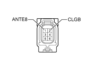
INSPECT ELECTRICAL KEY ANTENNA (OUTSIDE LUGGAGE)
-
Remove the electrical key antenna (outside luggage) Click here.
-
Measure the resistance according to the value(s) in the table below.
Standard Resistance Tester Connection Condition Specified Condition 1 (ANTE8) - 2 (CLGB) Always Below 1 Ω
NG
REPLACE ELECTRICAL KEY ANTENNA (OUTSIDE LUGGAGE) Click here
OK
-
-
REPLACE CERTIFICATION ECU (SMART KEY ECU ASSEMBLY)
-
Temporarily replace the certification ECU (smart key ECU assembly) with a new one.
Tech Tips
Refer to the Service Bulletin.
NEXT
-
-
CLEAR DTC
-
Clear the DTCs Click here.
NEXT
-
-
CHECK FOR DTC
-
Check for DTCs Click here.
OK DTC B27A8 is not output.
NG
REPLACE ELECTRICAL KEY ANTENNA (OUTSIDE LUGGAGE) Click here
OK 
END (CERTIFICATION ECU (SMART KEY ECU ASSEMBLY) WAS DEFECTIVE)
-