NETWORK GATEWAY ECU INSTALLATION

Tech Tips
-
Use the same procedure for RHD and LHD vehicles.
-
The procedure listed below is for LHD vehicles.
-
INSTALL NETWORK GATEWAY ECU
-
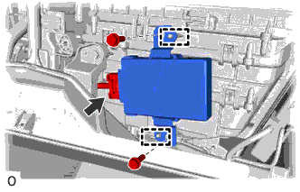
Align the 2 guides with the network gateway ECU.
-
Install the network gateway ECU with the 2 screws.
-
-
INSTALL GLOVE COMPARTMENT DOOR ASSEMBLY
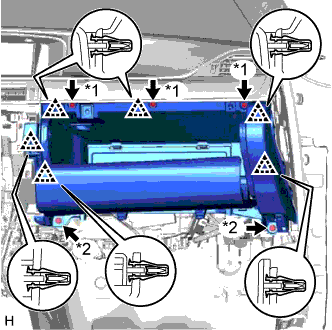
Text in Illustration *1 Screw <A> *2 Bolt <E>
-
Connect the connectors and attach the clamp.
-
Attach the 6 clips to install the glove compartment door assembly.
-
Install the 3 screws <A> and 2 bolts <E>.
-
-
INSTALL NO. 2 INSTRUMENT PANEL UNDER COVER SUB-ASSEMBLY
-
Connect the connectors and attach the clamp.
-
Attach the 5 clips and 2 guides to install the No. 2 instrument panel under cover sub-assembly.
-
-
INSTALL CENTER INSTRUMENT CLUSTER FINISH PANEL
-
Connect the connector.
-
Attach the 9 clips and guide to install the center instrument cluster finish panel.
-
-
INSTALL INSTRUMENT PANEL FINISH PANEL END RH
-
Attach the 5 clips and 2 guides to install the instrument panel finish panel end RH.
-
-
INSTALL INSTRUMENT SIDE PANEL RH
-
w/ Airbag Cut Off Switch:
-
Connect the connector.
-
-
Attach the 7 clips to install the instrument side panel RH.
-
-
INSTALL FRONT DOOR OPENING TRIM COVER RH
Tech Tips
Use the same procedure described for the LH side.
-
INSTALL FRONT DOOR SCUFF PLATE RH
Tech Tips
Use the same procedure described for the LH side.
-
CONNECT CABLE TO NEGATIVE BATTERY TERMINAL
Note
When disconnecting the cable, some systems need to be initialized after the cable is reconnected Click here.