CAN COMMUNICATION SYSTEM (for LHD) TERMINALS OF ECU

Note
-
After turning the engine switch off, waiting time may be required before disconnecting the cable from the negative (-) battery terminal. Therefore, make sure to read the disconnecting the cable from the negative (-) battery terminal notices before proceeding with work Click here.
-
Turn the engine switch off before measuring the resistances between CAN main bus lines and between CAN branch lines.
-
Turn the engine switch off before inspecting CAN bus lines for a ground short.
-
Before measuring the resistance of the CAN bus, turn the engine switch off and leave the vehicle for 1 minute or more without operating the key, switches or opening or closing the doors. After that, disconnect the cable from the negative (-) battery terminal and leave the vehicle for 1 minute or more before measuring the resistance.
-
This section describes the standard values for all CAN related components.
Tech Tips
-
Operating the engine switch, any other switches or a door triggers related ECU and sensor communication on the CAN. This communication will cause the resistance value to change.
-
Even after DTCs are cleared, if a DTC is stored again after driving the vehicle for a while, the malfunction may be occurring due to vibration of the vehicle. In such a case, wiggling the ECUs or wire harness while performing the inspection below may help determine the cause of the malfunction.
-
JUNCTION CONNECTOR
-
NO. 1 CAN JUNCTION CONNECTOR
Tech Tips
Connectors that connect to the CAN junction connector can be distinguished by color of their CAN bus lines. When the connectors have been disconnected from the CAN junction connector, reconnecting the connectors to non-original positions on the CAN junction connector does not affect system performance. However, it is preferred to reconnect the connectors to their original positions to avoid negative effects on the wiring such as tension on the wiring harnesses, and to make future maintenance easier.
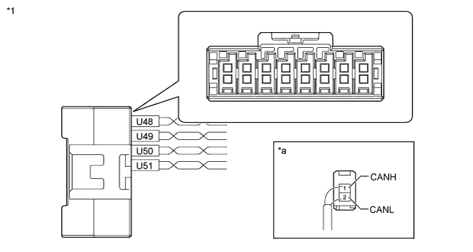
Text in Illustration *1 No. 1 CAN Junction Connector - - *a Rear view of wire harness connector
(to No. 1 CAN Junction Connector)
- - No. 1 CAN Junction Connector Wiring Color Connect to U48-1 (CANH) B Parking brake ECU assembly U48-2 (CANL) W U49-1 (CANH) R Main body ECU (multiplex network body ECU) U49-2 (CANL) W U50-1 (CANH) P No. 2 CAN junction connector U50-2 (CANL) W U51-1 (CANH) G ECM U51-2 (CANL) W -
NO. 2 CAN JUNCTION CONNECTOR
Tech Tips
Connectors that connect to the CAN junction connector can be distinguished by color of their CAN bus lines. When the connectors have been disconnected from the CAN junction connector, reconnecting the connectors to non-original positions on the CAN junction connector does not affect system performance. However, it is preferred to reconnect the connectors to their original positions to avoid negative effects on the wiring such as tension on the wiring harnesses, and to make future maintenance easier.
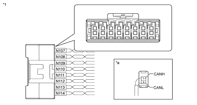
Text in Illustration *1 No. 2 CAN Junction Connector - - *a Rear view of wire harness connector
(to No. 2 CAN Junction Connector)
- - No. 2 CAN Junction Connector Wiring Color Connect to N107-1 (CANH) B No. 3 CAN junction connector N107-2 (CANL) W N108-1 (CANH) R Spiral with sensor cable sub-assembly (steering angle sensor) N108-2 (CANL) W N109-1 (CANH) G DLC3 N109-2 (CANL) W N110-1 (CANH) B Yaw rate sensor N110-2 (CANL) W N111-1 (CANH) Y Headlight swivel ECU assembly (AFS ECU) N111-2 (CANL) W N112-1 (CANH) V Combination meter assembly N112-2 (CANL) W N113-1 (CANH) P No. 1 CAN junction connector N113-2 (CANL) W N114-1 (CANH) L Brake actuator assembly (skid control ECU) N114-2 (CANL) W -
NO. 3 CAN JUNCTION CONNECTOR
Tech Tips
Connectors that connect to the CAN junction connector can be distinguished by color of their CAN bus lines. When the connectors have been disconnected from the CAN junction connector, reconnecting the connectors to non-original positions on the CAN junction connector does not affect system performance. However, it is preferred to reconnect the connectors to their original positions to avoid negative effects on the wiring such as tension on the wiring harnesses, and to make future maintenance easier.

Text in Illustration *1 No. 3 CAN Junction Connector - - *a Rear view of wire harness connector
(to No. 3 CAN Junction Connector)
- - No. 3 CAN Junction Connector Wiring Color Connect to N115-1 (CANH) L Power steering ECU assembly N115-2 (CANL) W N116-1 (CANH) G Network gateway ECU*1 N116-2 (CANL) W N117-1 (CANH) R Air conditioning amplifier assembly N117-2 (CANL) W N118-1 (CANH) Y Certification ECU (smart key ECU assembly) N118-2 (CANL) W N119-1 (CANH) V Front steering control ECU*2 N119-2 (CANL) W N120-1 (CANH) P Center airbag sensor assembly N120-2 (CANL) W N121-1 (CANH) B No. 2 CAN junction connector N121-2 (CANL) W N122-1 (CANH) B Multi-media module receiver assembly N122-2 (CANL) W
-
*1: w/ Network Gateway ECU
-
*2: w/ Variable Gear Ratio Steering System
-
-
NO. 1 JUNCTION CONNECTOR (w/ Network Gateway ECU)
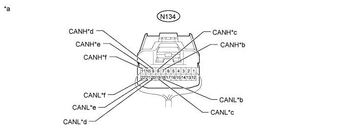
Text in Illustration *a Rear view of wire harness connector
(to No. 1 Junction Connector)
*b for Telematics Transceiver (w/ Telematics Transceiver) *c for Network Gateway ECU *d for Absorber Control ECU (w/ Adaptive Variable Suspension System) *e for No. 2 Junction Connector *f for 4WD ECU Assembly (for AWD) No. 1 Junction Connector Wiring Color Connect to N134-7 (CANH) W Telematics transceiver*1 N134-18 (CANL) LG N134-8 (CANH) P Network gateway ECU N134-19 (CANL) LG N134-9 (CANH) G Absorber control ECU*2 N134-20 (CANL) LG N134-10 (CANH) Y No. 2 junction connector N134-21 (CANL) LG N134-11 (CANH) V 4WD ECU assembly*3 N134-22 (CANL) LG
-
*1: w/ Telematics Transceiver
-
*2: w/ Adaptive Variable Suspension System
-
*3: for AWD
-
-
NO. 2 JUNCTION CONNECTOR (w/ Network Gateway ECU)
-
w/o Dynamic Rear Steering System:
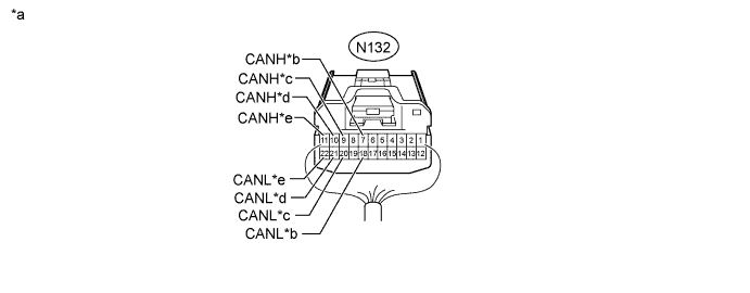
Text in Illustration *a Rear view of wire harness connector
(to No. 2 Junction Connector)
*b for No. 3 Junction Connector *c for Driving Support ECU Assembly (w/ Dynamic Radar Cruise Control System) *d for Clearance Warning ECU Assembly (w/ LEXUS Parking Assist-sensor System) *e for No. 1 Junction Connector - - No. 2 Junction Connector Wiring Color Connect to N132-7 (CANH) B No. 3 junction connector N132-18 (CANL) LG N132-9 (CANH) V Driving support ECU assembly*1 N132-20 (CANL) LG N132-10 (CANH) L Clearance warning ECU assembly*2 N132-21 (CANL) LG N132-11 (CANH) Y No. 1 junction connector N132-22 (CANL) LG
-
*1: w/ Dynamic Radar Cruise Control System
-
*2: w/ LEXUS Parking Assist-sensor System
-
-
w/ Dynamic Rear Steering System:
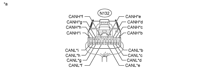
Text in Illustration *a Rear view of wire harness connector
(to No. 2 Junction Connector)
*b for Driving Support ECU Assembly [Sub Bus 19] (w/ Dynamic Radar Cruise Control System) *c for No. 3 Junction Connector [Sub Bus 19] *d for Brake Actuator Assembly (Skid Control ECU) [Sub Bus 19] *e for No. 5 Junction Connector *f for No. 3 Junction Connector [Sub Bus 18] *g for Driving Support ECU Assembly [Sub Bus 18] (w/ Dynamic Radar Cruise Control System) *h for Clearance Warning ECU Assembly (w/ LEXUS Parking Assist-sensor System) *i for No. 1 Junction Connector - - No. 2 Junction Connector Wiring Color Connect to N132-1 (CANH) G Driving support ECU assembly [Sub Bus 19]*1 N132-12 (CANL) SB N132-2 (CANH) R No. 3 junction connector [Sub Bus 19] N132-13 (CANL) SB N132-3 (CANH) Y Brake actuator assembly (skid control ECU) [Sub Bus 19] N132-14 (CANL) SB N132-5 (CANH) B No. 5 junction connector N132-16 (CANL) SB N132-7 (CANH) B No. 3 junction connector [Sub Bus 18] N132-18 (CANL) LG N132-9 (CANH) V Driving support ECU assembly [Sub Bus 18]*1 N132-20 (CANL) LG N132-10 (CANH) L Clearance warning ECU assembly*2 N132-21 (CANL) LG N132-11 (CANH) Y No. 1 junction connector N132-22 (CANL) LG
-
*1: w/ Dynamic Radar Cruise Control System
-
*2: w/ LEXUS Parking Assist-sensor System
-
-
-
NO. 3 JUNCTION CONNECTOR
-
w/o Dynamic Rear Steering System:
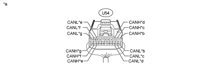
Text in Illustration *a Rear view of wire harness connector
(to No. 3 Junction Connector)
*b for Seat Belt Control ECU (w/ Pre-crash Safety System) *c for No. 4 Junction Connector [Sub Bus 2] (w/ Network Gateway ECU) *d for No. 2 Junction Connector [Sub Bus 2] (w/ Network Gateway ECU) *e for Main Body ECU (Multiplex Network Body ECU) [Sub Bus 1] *f for No. 6 Junction Connector *g for Luggage Closer Motor Assembly (w/ Power Trunk Lid System) - - No. 3 Junction Connector Wiring Color Connect to U54-1 (CANH) Y Seat belt control ECU*1 U54-12 (CANL) LG U54-2 (CANH) R No. 4 junction connector [Sub Bus 2]*2 U54-13 (CANL) LG U54-3 (CANH) B No. 2 junction connector [Sub Bus 2]*2 U54-14 (CANL) LG U54-20 (CANH) R Main body ECU (multiplex network body ECU) [Sub Bus 1] U54-9 (CANL) GR U54-21 (CANH) L No. 6 junction connector U54-10 (CANL) GR U54-22 (CANH) G Luggage closer motor assembly*3 U54-11 (CANL) GR
-
*1: w/ Pre-crash Safety System
-
*2: w/ Network Gateway ECU
-
*3: w/ Power Trunk Lid System
-
-
w/ Dynamic Rear Steering System:
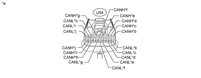
Text in Illustration *a Rear view of wire harness connector
(to No. 3 Junction Connector)
*b for Seat Belt Control ECU (w/ Pre-crash Safety System) *c for No. 4 Junction Connector [Sub Bus 18] *d for No. 2 Junction Connector [Sub Bus 18] *e for No. 10 Junction Connector *f for No. 2 Junction Connector [Sub Bus 19] *g for Rear Steering Control ECU [Sub Bus 19] *h for Main Body ECU (Multiplex Network Body ECU) [Sub Bus 1] *i for No. 6 Junction Connector *j for Luggage Closer Motor Assembly (w/ Power Trunk Lid System) No. 3 Junction Connector Wiring Color Connect to U54-1 (CANH) Y Seat belt control ECU*1 U54-12 (CANL) LG U54-2 (CANH) R No. 4 junction connector [Sub Bus 18] U54-13 (CANL) LG U54-3 (CANH) B No. 2 junction connector [Sub Bus 18] U54-14 (CANL) LG U54-5 (CANH) B No. 10 junction connector U54-16 (CANL) SB U54-6 (CANH) R No. 2 junction connector [Sub Bus 19] U54-17 (CANL) SB U54-7 (CANH) G Rear steering control ECU [Sub Bus 19] U54-18 (CANL) SB U54-20 (CANH) R Main body ECU (multiplex network body ECU) [Sub Bus 1] U54-9 (CANL) GR U54-21 (CANH) L No. 6 junction connector U54-10 (CANL) GR U54-22 (CANH) G Luggage closer motor assembly*2 U54-11 (CANL) GR
-
*1: w/ Pre-crash Safety System
-
*2: w/ Power Trunk Lid System
-
-
-
NO. 4 JUNCTION CONNECTOR (w/ Network Gateway ECU)
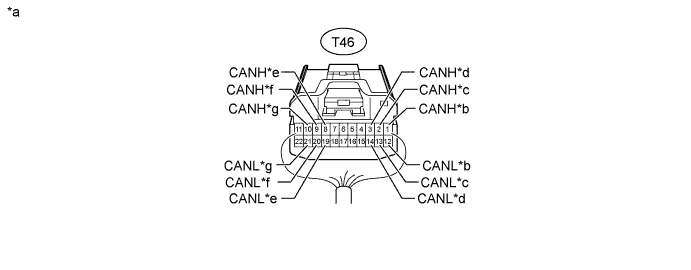
Text in Illustration *a Rear view of wire harness connector
(to No. 4 Junction Connector)
*b for No. 1 Night View ECU [Sub Bus 13] (w/ Night View System) *c for No. 12 Junction Connector (w/ Dynamic Radar Cruise Control System) *d for No. 7 Junction Connector (w/ Dynamic Radar Cruise Control System) *e for No. 3 Junction Connector [Sub Bus 2 (w/o Dynamic Rear Steering System) or Sub Bus 18 (w/ Dynamic Rear Steering System)] *f for No. 9 Junction Connector *g for Blind Spot Monitor Sensor RH (w/ Blind Spot Monitor System) *e - No. 4 Junction Connector Wiring Color Connect to T46-1 (CANH) G No. 1 night view ECU*1 T46-12 (CANL) W T46-2 (CANH) R No. 12 junction connector*2 T46-13 (CANL) W T46-3 (CANH) B No. 7 junction connector*2 T46-14 (CANL) W T46-8 (CANH) R No. 3 junction connector [Sub Bus 2*3 or Sub Bus 18*4] T46-19 (CANL) LG T46-9 (CANH) G No. 9 junction connector T46-20 (CANL) LG T46-10 (CANH) L Blind spot monitor sensor RH*4 T46-21 (CANL) LG
-
*1: w/ Night View System
-
*2: w/ Dynamic Radar Cruise Control System
-
*3: w/o Dynamic Rear Steering System
-
*4: w/ Dynamic Rear Steering System
-
*5: w/ Blind Spot Monitor System
-
-
NO. 5 JUNCTION CONNECTOR
-
w/o Dynamic Rear Steering System:
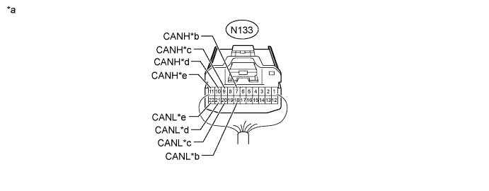
Text in Illustration *a Rear view of wire harness connector
(to No. 5 Junction Connector)
*b for No. 6 Junction Connector *c for Position Control ECU Assembly RH (for Luxury Seat Type) *d for No. 11 Junction Connector *e for Front Multiplex Network Door ECU RH - - No. 5 Junction Connector Wiring Color Connect to N133-7 (CANH) B No. 6 junction connector N133-18 (CANL) GR N133-9 (CANH) G Position control ECU assembly RH* N133-20 (CANL) GR N133-10 (CANH) L No. 11 junction connector N133-21 (CANL) GR N133-11 (CANH) Y Front multiplex network door ECU RH N133-22 (CANL) GR
-
*: for Luxury Seat Type
-
-
w/ Dynamic Rear Steering System:
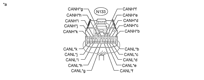
Text in Illustration *a Rear view of wire harness connector
(to No. 5 Junction Connector)
*b for ECM [Sub Bus 19] *c for Front Steering Control ECU [Sub Bus 19] *d for Absorber Control ECU [Sub Bus 19] (w/ Adaptive Variable Suspension System) *e for Network Gateway ECU [Sub Bus 19] *f for No. 2 Junction Connector [Sub Bus 19] *g for Power Steering ECU Assembly [Sub Bus 19] *h for No. 6 Junction Connector *i for Position Control ECU Assembly RH (for Luxury Seat Type) *j for No. 11 Junction Connector *k for Front Multiplex Network Door ECU RH - - No. 5 Junction Connector Wiring Color Connect to N133-1 (CANH) P ECM [Sub Bus 19] N133-12 (CANL) SB N133-2 (CANH) G Front steering control ECU [Sub Bus 19] N133-13 (CANL) SB N133-3 (CANH) L Absorber control ECU [Sub Bus 19]*1 N133-14 (CANL) SB N133-4 (CANH) V Network gateway ECU [Sub Bus 19] N133-15 (CANL) SB N133-5 (CANH) B No. 2 junction connector [Sub Bus 19] N133-16 (CANL) SB N133-6 (CANH) Y Power steering ECU assembly [Sub Bus 19] N133-17 (CANL) SB N133-7 (CANH) B No. 6 junction connector N133-18 (CANL) GR N133-9 (CANH) G Position control ECU assembly RH*2 N133-20 (CANL) GR N133-10 (CANH) L No. 11 junction connector N133-21 (CANL) GR N133-11 (CANH) Y Front multiplex network door ECU RH N133-22 (CANL) GR
-
*1: w/ Adaptive Variable Suspension System
-
*2: for Luxury Seat Type
-
-
-
NO. 6 JUNCTION CONNECTOR
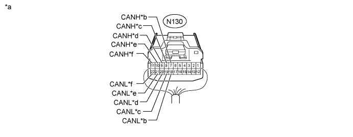
Text in Illustration *a Rear view of wire harness connector
(to No. 6 Junction Connector)
*b for Front Multiplex Network Door ECU LH *c for No. 3 Junction Connector *d
-
for Position Control ECU Assembly LH (except Standard Seat Type)
-
for Power Seat Switch Assembly (for Standard Seat Type)
*e for Multiplex Tilt and Telescopic ECU *f for No. 5 Junction Connector No. 6 Junction Connector Wiring Color Connect to N130-7 (CANH) Y Front multiplex network door ECU LH N130-18 (CANL) GR N130-8 (CANH) L No. 3 junction connector N130-19 (CANL) GR N130-9 (CANH) G
-
Position control ECU assembly LH*1
-
Power seat switch assembly*2
N130-20 (CANL) GR N130-10 (CANH) R Multiplex tilt and telescopic ECU N130-21 (CANL) GR N130-11 (CANH) B No. 5 junction connector N130-22 (CANL) GR
-
*1: except Standard Seat Type
-
*2: for Standard Seat Type
-
-
NO. 7 JUNCTION CONNECTOR (w/ Dynamic Radar Cruise Control System)
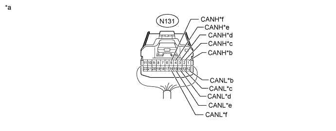
Text in Illustration *a Rear view of wire harness connector
(to No. 7 Junction Connector)
*b for No. 4 Junction Connector *c for Driver Monitor ECU Assembly (w/ Driver Monitor Camera) *d for Driving Support ECU Assembly *e for Lane Recognition Camera Sensor Assembly (w/ Lane-keeping Assist System) *f for Millimeter Wave Radar Sensor Assembly No. 7 Junction Connector Wiring Color Connect to N131-1 (CANH) B No. 4 junction connector N131-12 (CANL) W N131-2 (CANH) R Driver monitor ECU assembly*1 N131-13 (CANL) W N131-3 (CANH) G Driving support ECU assembly N131-14 (CANL) W N131-4 (CANH) L Lane recognition camera sensor assembly*2 N131-15 (CANL) W N131-5 (CANH) Y Millimeter wave radar sensor assembly N131-16 (CANL) W
-
*1: w/ Driver Monitor Camera
-
*2: w/ Lane-keeping Assist System
-
-
NO. 8 JUNCTION CONNECTOR
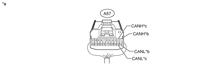
Text in Illustration *a Rear view of wire harness connector
(to No. 8 Junction Connector)
*b for ECM *c for Certification ECU (Smart Key ECU Assembly) - - No. 8 Junction Connector Wiring Color Connect to A57-1 (CANH) B ECM A57-12 (CANL) W A57-2 (CANH) G Certification ECU (smart key ECU assembly) A57-13 (CANL) W -
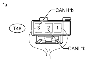
Text in Illustration *a Rear view of wire harness connector
(to No. 9 Junction Connector)
*b for No. 4 Junction Connector NO. 9 JUNCTION CONNECTOR (w/ Network Gateway ECU)
No. 9 Junction Connector Wiring Color Connect to T48-2 (CANL) LG No. 4 junction connector T48-3 (CANH) G -

Text in Illustration *a Rear view of wire harness connector
(to No. 10 Junction Connector)
*b for No. 3 Junction Connector NO. 10 JUNCTION CONNECTOR (w/ Dynamic Rear Steering System)
No. 10 Junction Connector Wiring Color Connect to U56-2 (CANL) SB No. 3 junction connector U56-3 (CANH) B -
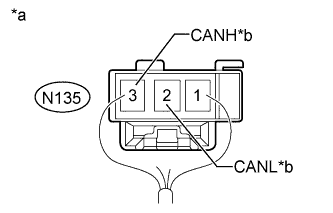
Text in Illustration *a Rear view of wire harness connector
(to No. 11 Junction Connector)
*b for No. 5 Junction Connector NO. 11 JUNCTION CONNECTOR
No. 11 Junction Connector Wiring Color Connect to N135-2 (CANL) GR No. 5 junction connector N135-3 (CANH) L -
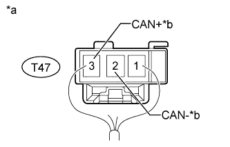
Text in Illustration *a Rear view of wire harness connector
(to No. 12 Junction Connector)
*b for No. 4 Junction Connector NO. 12 JUNCTION CONNECTOR (w/ Dynamic Radar Cruise Control System)
No. 12 Junction Connector Wiring Color Connect to T47-2 (CAN-) W No. 4 junction connector T47-3 (CAN+) R
-
-
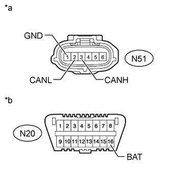
CHECK DLC3
-
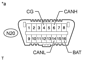
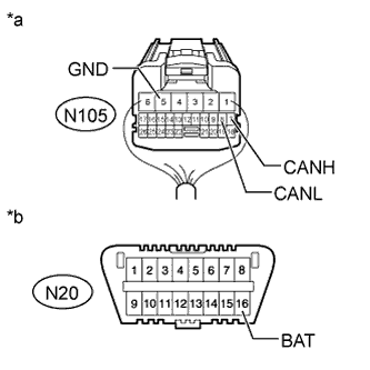
Text in Illustration *a Front view of DLC3 Disconnect the cable from the negative (-) battery terminal before measuring the resistances of the CAN main wire and CAN branch wire.
-
Measure the resistance according to the value(s) in the table below.
Terminal No. (Symbol) Wiring Color Terminal Description Condition Specified Condition N20-6 (CANH) - N20-14 (CANL) G - W HIGH-level CAN bus line - LOW-level CAN bus line Cable disconnected from negative (-) battery terminal 54 to 69 Ω N20-6 (CANH) - N20-4 (CG) G - W-B HIGH-level CAN bus line - Ground Cable disconnected from negative (-) battery terminal 200 Ω or higher N20-14 (CANL) - N20-4 (CG) W - W-B LOW-level CAN bus line - Ground Cable disconnected from negative (-) battery terminal 200 Ω or higher N20-6 (CANH) - N20-16 (BAT) G - Y HIGH-level CAN bus line - Battery positive (+) Cable disconnected from negative (-) battery terminal 6 kΩ or higher N20-14 (CANL) - N20-16 (BAT) W - Y LOW-level CAN bus line - Battery positive (+) Cable disconnected from negative (-) battery terminal 6 kΩ or higher
-
-
CHECK NETWORK GATEWAY ECU (w/ Network Gateway ECU)
-
w/o Dynamic Rear Steering System:
Text in Illustration *A V Bus *B Sub Bus 2 *a Component without harness connected
(Network Gateway ECU)
- -
-
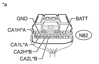
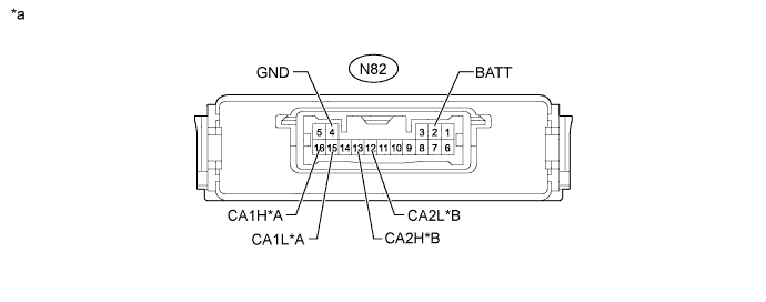
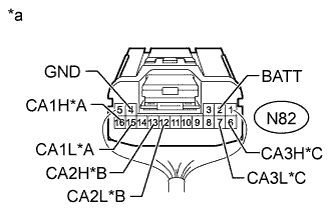
Text in Illustration *A V Bus *B Sub Bus 2 *a Rear view of wire harness connector
(to Network Gateway ECU)
Disconnect the network gateway ECU connector.
-
Measure the resistance according to the value(s) in the table below.
V Bus Terminal No. (Symbol) Wiring Color Terminal Description Condition Specified Condition N82-16 (CA1H) - N82-15 (CA1L) G - W HIGH-level CAN bus line - LOW-level CAN bus line Cable disconnected from negative (-) battery terminal 54 to 69 Ω N82-16 (CA1H) - N82-4 (GND) G - W-B HIGH-level CAN bus line - Ground Cable disconnected from negative (-) battery terminal 200 Ω or higher N82-15 (CA1L) - N82-4 (GND) W - W-B LOW-level CAN bus line - Ground Cable disconnected from negative (-) battery terminal 200 Ω or higher N82-16 (CA1H) - N82-2 (BATT) G - P HIGH-level CAN bus line - Battery positive (+) Cable disconnected from negative (-) battery terminal 6 kΩ or higher N82-15 (CA1L) - N82-2 (BATT) W - P LOW-level CAN bus line - Battery positive (+) Cable disconnected from negative (-) battery terminal 6 kΩ or higher Sub Bus 2 Terminal No. (Symbol) Wiring Color Terminal Description Condition Specified Condition N82-13 (CA2H) - N82-12 (CA2L) P - LG HIGH-level CAN bus line - LOW-level CAN bus line Cable disconnected from negative (-) battery terminal 108 to 132 Ω N82-13 (CA2H) - N82-4 (GND) P - W-B HIGH-level CAN bus line - Ground Cable disconnected from negative (-) battery terminal 200 Ω or higher N82-12 (CA2L) - N82-4 (GND) LG - W-B LOW-level CAN bus line - Ground Cable disconnected from negative (-) battery terminal 200 Ω or higher N82-13 (CA2H) - N82-2 (BATT) P - P HIGH-level CAN bus line - Battery positive (+) Cable disconnected from negative (-) battery terminal 6 kΩ or higher N82-12 (CA2L) - N82-2 (BATT) LG - P LOW-level CAN bus line - Battery positive (+) Cable disconnected from negative (-) battery terminal 6 kΩ or higher
-
-
w/ Dynamic Rear Steering System:
Text in Illustration *A V Bus *B Sub Bus 18 *C Sub Bus 19 - - *a Component without harness connected
(Network Gateway ECU)
- -
-
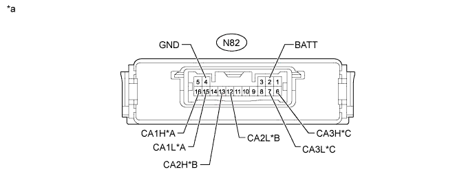
Text in Illustration *A V Bus *B Sub Bus 18 *C Sub Bus 19 *a Rear view of wire harness connector
(to Network Gateway ECU)
Disconnect the network gateway ECU connector.
-
Measure the resistance according to the value(s) in the table below.
V Bus Terminal No. (Symbol) Wiring Color Terminal Description Condition Specified Condition N82-16 (CA1H) - N82-15 (CA1L) G - W HIGH-level CAN bus line - LOW-level CAN bus line Cable disconnected from negative (-) battery terminal 54 to 69 Ω N82-16 (CA1H) - N82-4 (GND) G - W-B HIGH-level CAN bus line - Ground Cable disconnected from negative (-) battery terminal 200 Ω or higher N82-15 (CA1L) - N82-4 (GND) W - W-B LOW-level CAN bus line - Ground Cable disconnected from negative (-) battery terminal 200 Ω or higher N82-16 (CA1H) - N82-2 (BATT) G - P HIGH-level CAN bus line - Battery positive (+) Cable disconnected from negative (-) battery terminal 6 kΩ or higher N82-15 (CA1L) - N82-2 (BATT) W - P LOW-level CAN bus line - Battery positive (+) Cable disconnected from negative (-) battery terminal 6 kΩ or higher Sub Bus 18 Terminal No. (Symbol) Wiring Color Terminal Description Condition Specified Condition N82-13 (CA2H) - N82-12 (CA2L) P - LG HIGH-level CAN bus line - LOW-level CAN bus line Cable disconnected from negative (-) battery terminal 108 to 132 Ω N82-13 (CA2H) - N82-4 (GND) P - W-B HIGH-level CAN bus line - Ground Cable disconnected from negative (-) battery terminal 200 Ω or higher N82-12 (CA2L) - N82-4 (GND) LG - W-B LOW-level CAN bus line - Ground Cable disconnected from negative (-) battery terminal 200 Ω or higher N82-13 (CA2H) - N82-2 (BATT) P - P HIGH-level CAN bus line - Battery positive (+) Cable disconnected from negative (-) battery terminal 6 kΩ or higher N82-12 (CA2L) - N82-2 (BATT) LG - P LOW-level CAN bus line - Battery positive (+) Cable disconnected from negative (-) battery terminal 6 kΩ or higher Sub Bus 19 Terminal No. (Symbol) Wiring Color Terminal Description Condition Specified Condition N82-6 (CA3H) - N82-7 (CA3L) V - SB HIGH-level CAN bus line - LOW-level CAN bus line Cable disconnected from negative (-) battery terminal 54 to 69 Ω N82-6 (CA3H) - N82-4 (GND) V - W-B HIGH-level CAN bus line - Ground Cable disconnected from negative (-) battery terminal 200 Ω or higher N82-7 (CA3L) - N82-4 (GND) SB - W-B LOW-level CAN bus line - Ground Cable disconnected from negative (-) battery terminal 200 Ω or higher N82-6 (CA3H) - N82-2 (BATT) V - P HIGH-level CAN bus line - Battery positive (+) Cable disconnected from negative (-) battery terminal 6 kΩ or higher N82-7 (CA3L) - N82-2 (BATT) SB - P LOW-level CAN bus line - Battery positive (+) Cable disconnected from negative (-) battery terminal 6 kΩ or higher
-
-
-
CHECK ECM
Text in Illustration *A V Bus *B Sub Bus 19 (except AA81E) *C Sub Bus 19 (for AA81E) *D Sub Bus 15 *E Powertrain Bus - - *a Component without harness connected
(ECM)
- -
-
Disconnect the ECM connectors.
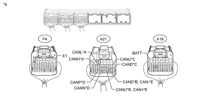
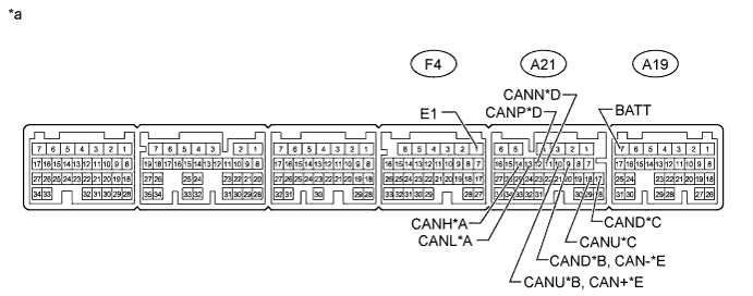
Text in Illustration *A V Bus *B Sub Bus 19 (except AA81E) *C Sub Bus 19 (for AA81E) *D Sub Bus 15 *E Powertrain Bus - - *a Rear view of wire harness connector
(to ECM)
- - -
Measure the resistance according to the value(s) in the table below.
V Bus Terminal No. (Symbol) Wiring Color Terminal Description Condition Specified Condition A21-14 (CANH) - A21-13 (CANL) G - W HIGH-level CAN bus line - LOW-level CAN bus line Cable disconnected from negative (-) battery terminal 108 to 132 Ω A21-14 (CANH) - F4-1 (E1) G - BR HIGH-level CAN bus line - Ground Cable disconnected from negative (-) battery terminal 200 Ω or higher A21-13 (CANL) - F4-1 (E1) W - BR LOW-level CAN bus line - Ground Cable disconnected from negative (-) battery terminal 200 Ω or higher A21-14 (CANH) - A19-7 (BATT) G - L HIGH-level CAN bus line - Battery positive (+) Cable disconnected from negative (-) battery terminal 6 kΩ or higher A21-13 (CANL) - A19-7 (BATT) W - L LOW-level CAN bus line - Battery positive (+) Cable disconnected from negative (-) battery terminal 6 kΩ or higher Sub Bus 19 (except AA81E) Terminal No. (Symbol) Wiring Color Terminal Description Condition Specified Condition A21-10 (CANU) - A21-9 (CAND) P - SB HIGH-level CAN bus line - LOW-level CAN bus line Cable disconnected from negative (-) battery terminal 108 to 132 Ω A21-10 (CANU) - F4-1 (E1) P - BR HIGH-level CAN bus line - Ground Cable disconnected from negative (-) battery terminal 200 Ω or higher A21-9 (CAND) - F4-1 (E1) SB - BR LOW-level CAN bus line - Ground Cable disconnected from negative (-) battery terminal 200 Ω or higher A21-10 (CANU) - A19-7 (BATT) P - L HIGH-level CAN bus line - Battery positive (+) Cable disconnected from negative (-) battery terminal 6 kΩ or higher A21-9 (CAND) - A19-7 (BATT) SB - L LOW-level CAN bus line - Battery positive (+) Cable disconnected from negative (-) battery terminal 6 kΩ or higher Sub Bus 19 (for AA81E) Terminal No. (Symbol) Wiring Color Terminal Description Condition Specified Condition A21-18 (CANU) - A21-17 (CAND) P - SB HIGH-level CAN bus line - LOW-level CAN bus line Cable disconnected from negative (-) battery terminal 108 to 132 Ω A21-18 (CANU) - F4-1 (E1) P - BR HIGH-level CAN bus line - Ground Cable disconnected from negative (-) battery terminal 200 Ω or higher A21-17 (CAND) - F4-1 (E1) SB - BR LOW-level CAN bus line - Ground Cable disconnected from negative (-) battery terminal 200 Ω or higher A21-18 (CANU) - A19-7 (BATT) P - L HIGH-level CAN bus line - Battery positive (+) Cable disconnected from negative (-) battery terminal 6 kΩ or higher A21-17 (CAND) - A19-7 (BATT) SB - L LOW-level CAN bus line - Battery positive (+) Cable disconnected from negative (-) battery terminal 6 kΩ or higher Sub Bus 15 Terminal No. (Symbol) Wiring Color Terminal Description Condition Specified Condition A21-12 (CANP) - A21-11 (CANN) B - W HIGH-level CAN bus line - LOW-level CAN bus line Cable disconnected from negative (-) battery terminal 108 to 132 Ω A21-12 (CANP) - F4-1 (E1) B - BR HIGH-level CAN bus line - Ground Cable disconnected from negative (-) battery terminal 200 Ω or higher A21-11 (CANN) - F4-1 (E1) W - BR LOW-level CAN bus line - Ground Cable disconnected from negative (-) battery terminal 200 Ω or higher A21-12 (CANP) - A19-7 (BATT) B - L HIGH-level CAN bus line - Battery positive (+) Cable disconnected from negative (-) battery terminal 6 kΩ or higher A21-11 (CANN) - A19-7 (BATT) W - L LOW-level CAN bus line - Battery positive (+) Cable disconnected from negative (-) battery terminal 6 kΩ or higher Powertrain Bus Terminal No. (Symbol) Wiring Color Terminal Description Condition Specified Condition A21-10 (CAN+) - A21-9 (CAN-) R - L HIGH-level CAN bus line - LOW-level CAN bus line Cable disconnected from negative (-) battery terminal 108 to 132 Ω A21-10 (CAN+) - F4-1 (E1) R - BR HIGH-level CAN bus line - Ground Cable disconnected from negative (-) battery terminal 200 Ω or higher A21-9 (CAN-) - F4-1 (E1) L - BR LOW-level CAN bus line - Ground Cable disconnected from negative (-) battery terminal 200 Ω or higher A21-10 (CAN+) - A19-7 (BATT) R - L HIGH-level CAN bus line - Battery positive (+) Cable disconnected from negative (-) battery terminal 6 kΩ or higher A21-9 (CAN-) - A19-7 (BATT) L - L LOW-level CAN bus line - Battery positive (+) Cable disconnected from negative (-) battery terminal 6 kΩ or higher
-
-
CHECK CERTIFICATION ECU (SMART KEY ECU ASSEMBLY)
Text in Illustration *A V Bus *B Sub Bus 15 *a Component without harness connected
(Certification ECU [Smart Key ECU Assembly])
- -
-
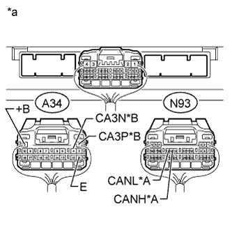
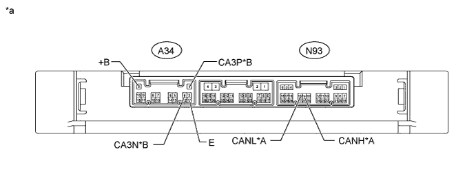
Text in Illustration *A V Bus *B Sub Bus 15 *a Rear view of wire harness connector
(to Certification ECU [Smart Key ECU Assembly])
Disconnect the certification ECU (smart key ECU assembly) connectors.
-
Measure the resistance according to the value(s) in the table below.
V Bus Terminal No. (Symbol) Wiring Color Terminal Description Condition Specified Condition N93-14 (CANH) - N93-15 (CANL) Y - W HIGH-level CAN bus line - LOW-level CAN bus line Cable disconnected from negative (-) battery terminal 108 to 132 Ω N93-14 (CANH) - A34-11 (E) Y - W-B HIGH-level CAN bus line - Ground Cable disconnected from negative (-) battery terminal 200 Ω or higher N93-15 (CANL) - A34-11 (E) W - W-B LOW-level CAN bus line - Ground Cable disconnected from negative (-) battery terminal 200 Ω or higher N93-14 (CANH) - A34-2 (+B) Y - W HIGH-level CAN bus line - Battery positive (+) Cable disconnected from negative (-) battery terminal 6 kΩ or higher N93-15 (CANL) - A34-2 (+B) W - W LOW-level CAN bus line - Battery positive (+) Cable disconnected from negative (-) battery terminal 6 kΩ or higher Sub Bus 15 Terminal No. (Symbol) Wiring Color Terminal Description Condition Specified Condition A34-1 (CA3P) - A34-4 (CA3N) G - W HIGH-level CAN bus line - LOW-level CAN bus line Cable disconnected from negative (-) battery terminal 108 to 132 Ω A34-1 (CA3P) - A34-11 (E) G - W-B HIGH-level CAN bus line - Ground Cable disconnected from negative (-) battery terminal 200 Ω or higher A34-4 (CA3N) - A34-11 (E) W - W-B LOW-level CAN bus line - Ground Cable disconnected from negative (-) battery terminal 200 Ω or higher A34-1 (CA3P) - A34-2 (+B) G - W HIGH-level CAN bus line - Battery positive (+) Cable disconnected from negative (-) battery terminal 6 kΩ or higher A34-4 (CA3N) - A34-2 (+B) W - W LOW-level CAN bus line - Battery positive (+) Cable disconnected from negative (-) battery terminal 6 kΩ or higher
-
-
CHECK COWL SIDE JUNCTION BLOCK LH AND MAIN BODY ECU (MULTIPLEX NETWORK BODY ECU)
Text in Illustration *A V Bus *B Sub Bus 1 *1 Main Body ECU (Multiplex Network Body ECU) - - *a Component without harness connected
(Main Body ECU [Multiplex Network Body ECU])
- -
-
Remove the main body ECU (multiplex network body ECU) from the cowl side junction block LH Click here.
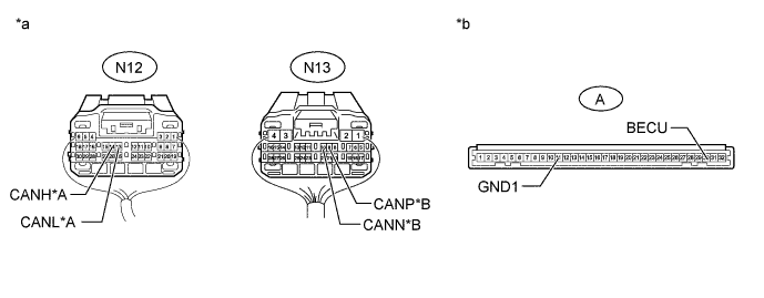
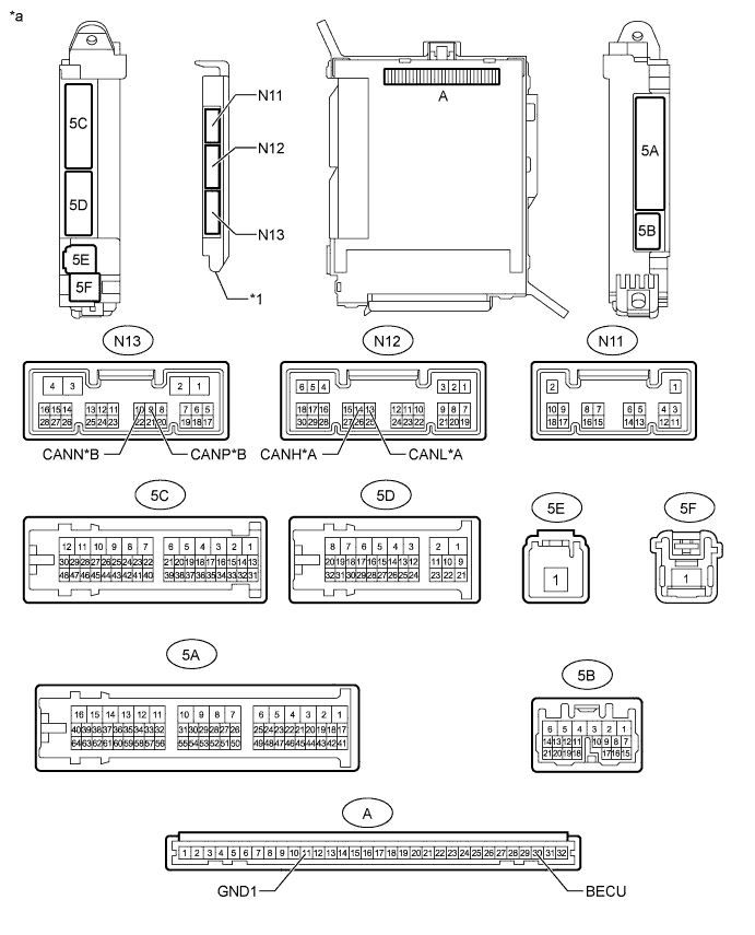
Text in Illustration *A V Bus *B Sub Bus 1 *a Rear view of wire harness connector
(to Cowl Side Junction Block LH)
*b Front view of wire harness connector
(to Main Body ECU [Multiplex Network Body ECU])
-
Reconnect the cowl side junction block LH connectors.
-
Measure the resistance according to the value(s) in the table below.
V Bus Terminal No. (Symbol) Wiring Color Terminal Description Condition Specified Condition N12-14 (CANH) - N12-13 (CANL) R - W HIGH-level CAN bus line - LOW-level CAN bus line Cable disconnected from negative (-) battery terminal 54 to 69 Ω N12-14 (CANH) - A-11 (GND1) R - None HIGH-level CAN bus line - Ground Cable disconnected from negative (-) battery terminal 200 Ω or higher N12-13 (CANL) - A-11 (GND1) W - None LOW-level CAN bus line - Ground Cable disconnected from negative (-) battery terminal 200 Ω or higher N12-14 (CANH) - A-30 (BECU) R - None HIGH-level CAN bus line - Battery positive (+) Cable disconnected from negative (-) battery terminal 6 kΩ or higher N12-13 (CANL) - A-30 (BECU) W - None LOW-level CAN bus line - Battery positive (+) Cable disconnected from negative (-) battery terminal 6 kΩ or higher Sub Bus 1 Terminal No. (Symbol) Wiring Color Terminal Description Condition Specified Condition N13-9 (CANP) - N13-10 (CANN) R - GR HIGH-level CAN bus line - LOW-level CAN bus line Cable disconnected from negative (-) battery terminal 108 to 132 Ω N13-9 (CANP) - A-11 (GND1) R - None HIGH-level CAN bus line - Ground Cable disconnected from negative (-) battery terminal 200 Ω or higher N13-10 (CANN) - A-11 (GND1) GR - None LOW-level CAN bus line - Ground Cable disconnected from negative (-) battery terminal 200 Ω or higher N13-9 (CANP) - A-30 (BECU) R - None HIGH-level CAN bus line - Battery positive (+) Cable disconnected from negative (-) battery terminal 6 kΩ or higher N13-10 (CANN) - A-30 (BECU) GR - None LOW-level CAN bus line - Battery positive (+) Cable disconnected from negative (-) battery terminal 6 kΩ or higher
-
-
CHECK BRAKE ACTUATOR ASSEMBLY (SKID CONTROL ECU)
Text in Illustration *A V Bus *B Sub Bus 19 *a Component without harness connected
(Brake Actuator Assembly [Skid Control ECU])
-
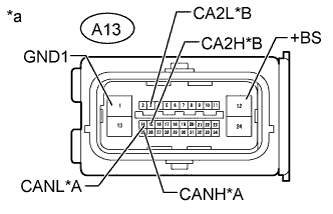
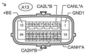
Text in Illustration *A V Bus *B Sub Bus 19 *a Front view of wire harness connector
(to Brake Actuator Assembly [Skid Control ECU])
Disconnect the brake actuator assembly (skid control ECU) connector.
-
Measure the resistance according to the value(s) in the table below.
V Bus Terminal No. (Symbol) Wiring Color Terminal Description Condition Specified Condition A13-25 (CANH) - A13-14 (CANL) L - W HIGH-level CAN bus line - LOW-level CAN bus line Cable disconnected from negative (-) battery terminal 54 to 69 Ω A13-25 (CANH) - A13-1 (GND1) L - W-B HIGH-level CAN bus line - Ground Cable disconnected from negative (-) battery terminal 200 Ω or higher A13-14 (CANL) - A13-1 (GND1) W - W-B LOW-level CAN bus line - Ground Cable disconnected from negative (-) battery terminal 200 Ω or higher A13-25 (CANH) - A13-12 (+BS) L - R HIGH-level CAN bus line - Battery positive (+) Cable disconnected from negative (-) battery terminal 6 kΩ or higher A13-14 (CANL) - A13-12 (+BS) W - R LOW-level CAN bus line - Battery positive (+) Cable disconnected from negative (-) battery terminal 6 kΩ or higher Sub Bus 19 Terminal No. (Symbol) Wiring Color Terminal Description Condition Specified Condition A13-15 (CA2H) - A13-3 (CA2L) Y - SB HIGH-level CAN bus line - LOW-level CAN bus line Cable disconnected from negative (-) battery terminal 54 to 69 Ω A13-15 (CA2H) - A13-1 (GND1) Y - W-B HIGH-level CAN bus line - Ground Cable disconnected from negative (-) battery terminal 200 Ω or higher A13-3 (CA2L) - A13-1 (GND1) SB - W-B LOW-level CAN bus line - Ground Cable disconnected from negative (-) battery terminal 200 Ω or higher A13-15 (CA2H) - A13-12 (+BS) Y - R HIGH-level CAN bus line - Battery positive (+) Cable disconnected from negative (-) battery terminal 6 kΩ or higher A13-3 (CA2L) - A13-12 (+BS) SB - R LOW-level CAN bus line - Battery positive (+) Cable disconnected from negative (-) battery terminal 6 kΩ or higher
-
-
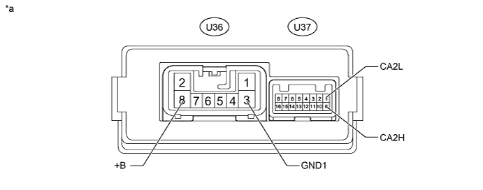
CHECK PARKING BRAKE ECU ASSEMBLY
Text in Illustration *a Component without harness connected
(Parking Brake ECU Assembly)
- -
-
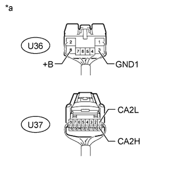
Text in Illustration *a Rear view of wire harness connector
(to Parking Brake ECU Assembly)
Disconnect the parking brake ECU assembly connectors.
-
Measure the resistance according to the value(s) in the table below.
Terminal No. (Symbol) Wiring Color Terminal Description Condition Specified Condition U37-9 (CA2H) - U37-1 (CA2L) B - W HIGH-level CAN bus line - LOW-level CAN bus line Cable disconnected from negative (-) battery terminal 54 to 69 Ω U37-9 (CA2H) - U36-3 (GND1) B - W-B HIGH-level CAN bus line - Ground Cable disconnected from negative (-) battery terminal 200 Ω or higher U37-1 (CA2L) - U36-3 (GND1) W - W-B LOW-level CAN bus line - Ground Cable disconnected from negative (-) battery terminal 200 Ω or higher U37-9 (CA2H) - U36-8 (+B) B - B HIGH-level CAN bus line - Battery positive (+) Cable disconnected from negative (-) battery terminal 6 kΩ or higher U37-1 (CA2L) - U36-8 (+B) W - B LOW-level CAN bus line - Battery positive (+) Cable disconnected from negative (-) battery terminal 6 kΩ or higher
-
-
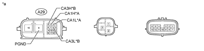
CHECK POWER STEERING ECU ASSEMBLY
Text in Illustration *A V Bus *B Sub Bus 19 *a Component without harness connected
(Power Steering ECU Assembly)
- -
-
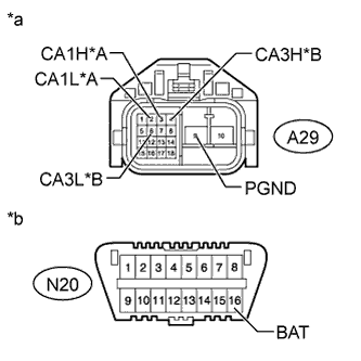
Text in Illustration *A V Bus *B Sub Bus 19 *a Front view of wire harness connector
(to Power Steering ECU Assembly)
*b Front view of DLC3 Disconnect the power steering ECU assembly connector.
-
Measure the resistance according to the value(s) in the table below.
V Bus Terminal No. (Symbol) Wiring Color Terminal Description Condition Specified Condition A29-3 (CA1H) - A29-2 (CA1L) L - W HIGH-level CAN bus line - LOW-level CAN bus line Cable disconnected from negative (-) battery terminal 54 to 69 Ω A29-3 (CA1H) - A29-9 (PGND) L - B HIGH-level CAN bus line - Ground Cable disconnected from negative (-) battery terminal 200 Ω or higher A29-2 (CA1L) - A29-9 (PGND) W - B LOW-level CAN bus line - Ground Cable disconnected from negative (-) battery terminal 200 Ω or higher A29-3 (CA1H) - N20-16 (BAT) L - Y HIGH-level CAN bus line - Battery positive (+) Cable disconnected from negative (-) battery terminal 6 kΩ or higher A29-2 (CA1L) - N20-16 (BAT) W - Y LOW-level CAN bus line - Battery positive (+) Cable disconnected from negative (-) battery terminal 6 kΩ or higher Sub Bus 19 Terminal No. (Symbol) Wiring Color Terminal Description Condition Specified Condition A29-4 (CA3H) - A29-6 (CA3L) Y - SB HIGH-level CAN bus line - LOW-level CAN bus line Cable disconnected from negative (-) battery terminal 54 to 69 Ω A29-4 (CA3H) - A29-9 (PGND) Y - B HIGH-level CAN bus line - Ground Cable disconnected from negative (-) battery terminal 200 Ω or higher A29-6 (CA3L) - A29-9 (PGND) SB - B LOW-level CAN bus line - Ground Cable disconnected from negative (-) battery terminal 200 Ω or higher A29-4 (CA3H) - N20-16 (BAT) Y - Y HIGH-level CAN bus line - Battery positive (+) Cable disconnected from negative (-) battery terminal 6 kΩ or higher A29-6 (CA3L) - N20-16 (BAT) SB - Y LOW-level CAN bus line - Battery positive (+) Cable disconnected from negative (-) battery terminal 6 kΩ or higher
-
-
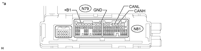
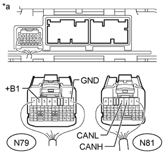
CHECK AIR CONDITIONING AMPLIFIER ASSEMBLY
Text in Illustration *a Component without harness connected
(Air Conditioning Amplifier Assembly)
- -
-
Text in Illustration *a Rear view of wire harness connector
(to Air Conditioning Amplifier Assembly)
Disconnect the air conditioning amplifier assembly connectors.
-
Measure the resistance according to the value(s) in the table below.
Terminal No. (Symbol) Wiring Color Terminal Description Condition Specified Condition N81-3 (CANH) - N81-4 (CANL) R - W HIGH-level CAN bus line - LOW-level CAN bus line Cable disconnected from negative (-) battery terminal 54 to 69 Ω N81-3 (CANH) - N79-1 (GND) R - W-B HIGH-level CAN bus line - Ground Cable disconnected from negative (-) battery terminal 200 Ω or higher N81-4 (CANL) - N79-1 (GND) W - W-B LOW-level CAN bus line - Ground Cable disconnected from negative (-) battery terminal 200 Ω or higher N81-3 (CANH) - N79-6 (+B1) R - W HIGH-level CAN bus line - Battery positive (+) Cable disconnected from negative (-) battery terminal 6 kΩ or higher N81-4 (CANL) - N79-6 (+B1) W - W LOW-level CAN bus line - Battery positive (+) Cable disconnected from negative (-) battery terminal 6 kΩ or higher
-
-
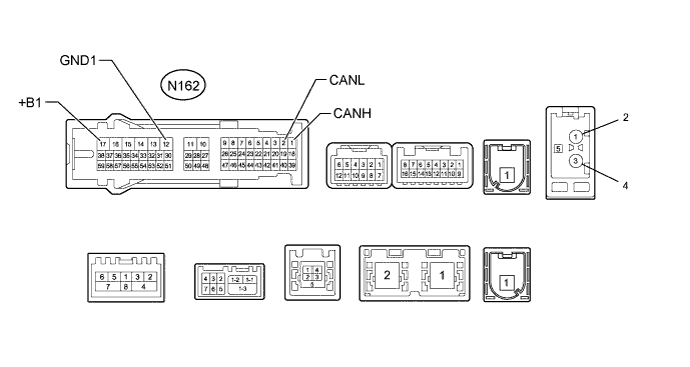
CHECK MULTI-MEDIA MODULE RECEIVER ASSEMBLY
Text in Illustration *a Component without harness connected
(Multi-media Module Receiver Assembly)
- -
-
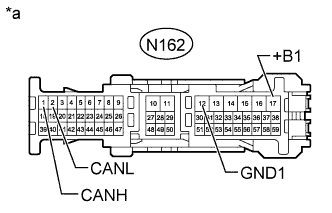
Text in Illustration *a Front view of wire harness connector
(to Multi-media Module Receiver Assembly)
Disconnect the multi-media module receiver assembly connector.
-
Measure the resistance according to the value(s) in the table below.
Terminal No. (Symbol) Wiring Color Terminal Description Condition Specified Condition N162-1 (CANH) - N162-2 (CANL) B - W HIGH-level CAN bus line - LOW-level CAN bus line Cable disconnected from negative (-) battery terminal 54 to 69 Ω N162-1 (CANH) - N162-12 (GND1) B - W-B HIGH-level CAN bus line - Ground Cable disconnected from negative (-) battery terminal 200 Ω or higher N162-2 (CANL) - N162-12 (GND1) W - W-B LOW-level CAN bus line - Ground Cable disconnected from negative (-) battery terminal 200 Ω or higher N162-1 (CANH) - N162-17 (+B1) B - L HIGH-level CAN bus line - Battery positive (+) Cable disconnected from negative (-) battery terminal 6 kΩ or higher N162-2 (CANL) - N162-17 (+B1) W - L LOW-level CAN bus line - Battery positive (+) Cable disconnected from negative (-) battery terminal 6 kΩ or higher
-
-
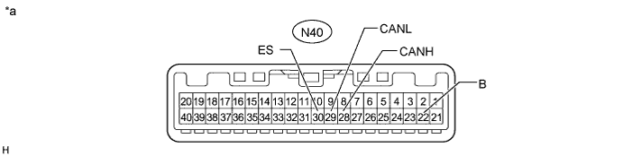
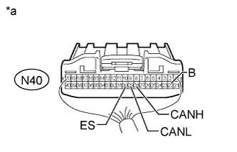
CHECK COMBINATION METER ASSEMBLY
Text in Illustration *a Component without harness connected
(Combination Meter Assembly)
- -
-
Text in Illustration *a Rear view of wire harness connector
(to Combination Meter Assembly)
Disconnect the combination meter assembly connector.
-
Measure the resistance according to the value(s) in the table below.
Terminal No. (Symbol) Wiring Color Terminal Description Condition Specified Condition N40-28 (CANH) - N40-29 (CANL) V - W HIGH-level CAN bus line - LOW-level CAN bus line Cable disconnected from negative (-) battery terminal 54 to 69 Ω N40-28 (CANH) - N40-30 (ES) V - W-B HIGH-level CAN bus line - Ground Cable disconnected from negative (-) battery terminal 200 Ω or higher N40-29 (CANL) - N40-30 (ES) W - W-B LOW-level CAN bus line - Ground Cable disconnected from negative (-) battery terminal 200 Ω or higher N40-28 (CANH) - N40-22 (B) V - P HIGH-level CAN bus line - Battery positive (+) Cable disconnected from negative (-) battery terminal 6 kΩ or higher N40-29 (CANL) - N40-22 (B) W - P LOW-level CAN bus line - Battery positive (+) Cable disconnected from negative (-) battery terminal 6 kΩ or higher
-
-
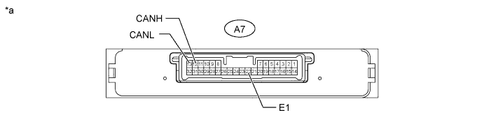
CHECK HEADLIGHT SWIVEL ECU ASSEMBLY (AFS ECU)
Text in Illustration *a Component without harness connected
(Headlight Swivel ECU Assembly [AFS ECU])
- -
-
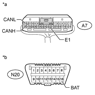
Text in Illustration *a Rear view of wire harness connector
(to Headlight Swivel ECU Assembly [AFS ECU])
*b Front view of DLC3 Disconnect the headlight swivel ECU assembly (AFS ECU) connector.
-
Measure the resistance according to the value(s) in the table below.
Terminal No. (Symbol) Wiring Color Terminal Description Condition Specified Condition A7-12 (CANH) - A7-13 (CANL) Y - W HIGH-level CAN bus line - LOW-level CAN bus line Cable disconnected from negative (-) battery terminal 54 to 69 Ω A7-12 (CANH) - A7-22 (E1) Y - W-B HIGH-level CAN bus line - Ground Cable disconnected from negative (-) battery terminal 200 Ω or higher A7-13 (CANL) - A7-22 (E1) W - W-B LOW-level CAN bus line - Ground Cable disconnected from negative (-) battery terminal 200 Ω or higher A7-12 (CANH) - N20-16 (BAT) Y - Y HIGH-level CAN bus line - Battery positive (+) Cable disconnected from negative (-) battery terminal 6 kΩ or higher A7-13 (CANL) - N20-16 (BAT) W - Y LOW-level CAN bus line - Battery positive (+) Cable disconnected from negative (-) battery terminal 6 kΩ or higher
-
-
CHECK CENTER AIRBAG SENSOR ASSEMBLY
Text in Illustration *a Component without harness connected
(Center Airbag Sensor Assembly)
- -
-
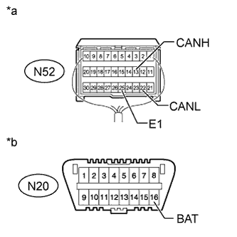
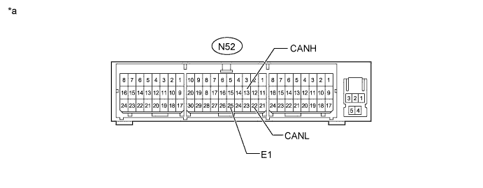
Text in Illustration *a Rear view of wire harness connector
(to Center Airbag Sensor Assembly)
*b Front view of DLC3 Disconnect the center airbag sensor assembly connector Click here.
-
Measure the resistance according to the value(s) in the table below.
Terminal No. (Symbol) Wiring Color Terminal Description Condition Specified Condition N52-13 (CANH) - N52-22 (CANL) P - W HIGH-level CAN bus line - LOW-level CAN bus line Cable disconnected from negative (-) battery terminal 54 to 69 Ω N52-13 (CANH) - N52-25 (E1) P - W-B HIGH-level CAN bus line - Ground Cable disconnected from negative (-) battery terminal 200 Ω or higher N52-22 (CANL) - N52-25 (E1) W - W-B LOW-level CAN bus line - Ground Cable disconnected from negative (-) battery terminal 200 Ω or higher N52-13 (CANH) - N20-16 (BAT) P - Y HIGH-level CAN bus line - Battery positive (+) Cable disconnected from negative (-) battery terminal 6 kΩ or higher N52-22 (CANL) - N20-16 (BAT) W - Y LOW-level CAN bus line - Battery positive (+) Cable disconnected from negative (-) battery terminal 6 kΩ or higher
-
-
CHECK SPIRAL WITH SENSOR CABLE SUB-ASSEMBLY (STEERING ANGLE SENSOR)
Text in Illustration *A w/ Variable Gear Ratio Steering System *B w/o Variable Gear Ratio Steering System *a Component without harness connected
(Spiral with Sensor Cable Sub-assembly [Steering Angle Sensor])
- -
-
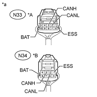
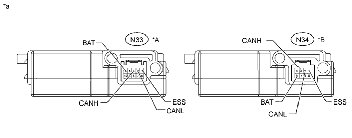
Text in Illustration *A w/ Variable Gear Ratio Steering System *B w/o Variable Gear Ratio Steering System *a Rear view of wire harness connector
(to Spiral with Sensor Cable Sub-assembly [Steering Angle Sensor])
Disconnect the spiral with sensor cable sub-assembly (steering angle sensor) connector.
-
Measure the resistance according to the value(s) in the table below.
w/ Variable Gear Ratio Steering System Terminal No. (Symbol) Wiring Color Terminal Description Condition Specified Condition N33-3 (CANH) - N33-2 (CANL) R - W HIGH-level CAN bus line - LOW-level CAN bus line Cable disconnected from negative (-) battery terminal 54 to 69 Ω N33-3 (CANH) - N33-1 (ESS) R - W-B HIGH-level CAN bus line - Ground Cable disconnected from negative (-) battery terminal 200 Ω or higher N33-2 (CANL) - N33-1 (ESS) W - W-B LOW-level CAN bus line - Ground Cable disconnected from negative (-) battery terminal 200 Ω or higher N33-3 (CANH) - N33-5 (BAT) R - P HIGH-level CAN bus line - Battery positive (+) Cable disconnected from negative (-) battery terminal 6 kΩ or higher N33-2 (CANL) - N33-5 (BAT) W - P LOW-level CAN bus line - Battery positive (+) Cable disconnected from negative (-) battery terminal 6 kΩ or higher w/o Variable Gear Ratio Steering System Terminal No. (Symbol) Wiring Color Terminal Description Condition Specified Condition N34-3 (CANH) - N34-2 (CANL) R - W HIGH-level CAN bus line - LOW-level CAN bus line Cable disconnected from negative (-) battery terminal 54 to 69 Ω N34-3 (CANH) - N34-1 (ESS) R - W-B HIGH-level CAN bus line - Ground Cable disconnected from negative (-) battery terminal 200 Ω or higher N34-2 (CANL) - N34-1 (ESS) W - W-B LOW-level CAN bus line - Ground Cable disconnected from negative (-) battery terminal 200 Ω or higher N34-3 (CANH) - N34-8 (BAT) R - GR HIGH-level CAN bus line - Battery positive (+) Cable disconnected from negative (-) battery terminal 6 kΩ or higher N34-2 (CANL) - N34-8 (BAT) W - GR LOW-level CAN bus line - Battery positive (+) Cable disconnected from negative (-) battery terminal 6 kΩ or higher
-
-
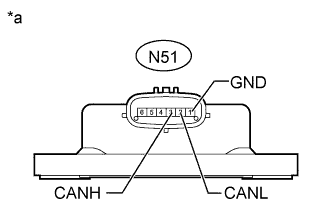
CHECK YAW RATE SENSOR
Text in Illustration *a Component without harness connected
(Yaw Rate Sensor)
-
Text in Illustration *a Front view of wire harness connector
(to Yaw Rate Sensor)
*b Front view of DLC3 Disconnect the yaw rate sensor connector.
-
Measure the resistance according to the value(s) in the table below.
Terminal No. (Symbol) Wiring Color Terminal Description Condition Specified Condition N51-3 (CANH) - N51-2 (CANL) B - W HIGH-level CAN bus line - LOW-level CAN bus line Cable disconnected from negative (-) battery terminal 54 to 69 Ω N51-3 (CANH) - N51-1 (GND) B - W-B HIGH-level CAN bus line - Ground Cable disconnected from negative (-) battery terminal 200 Ω or higher N51-2 (CANL) - N51-1 (GND) W - W-B LOW-level CAN bus line - Ground Cable disconnected from negative (-) battery terminal 200 Ω or higher N51-3 (CANH) - N20-16 (BAT) B - Y HIGH-level CAN bus line - Battery positive (+) Cable disconnected from negative (-) battery terminal 6 kΩ or higher N51-2 (CANL) - N20-16 (BAT) W - Y LOW-level CAN bus line - Battery positive (+) Cable disconnected from negative (-) battery terminal 6 kΩ or higher
-
-
CHECK FRONT STEERING CONTROL ECU (w/ Variable Gear Ratio Steering System)
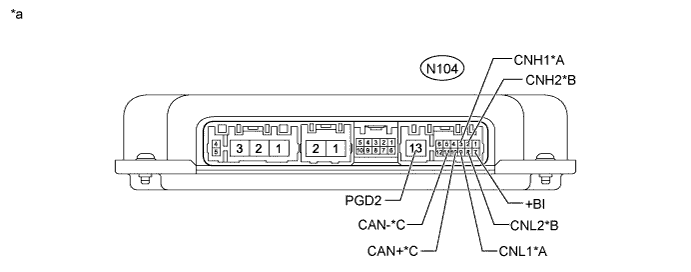
Text in Illustration *A V Bus *B Sub Bus 19 *C Local Bus - - *a Component without harness connected
(Front Steering Control ECU)
- -
-
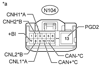
Text in Illustration *A V Bus *B Sub Bus 19 *C Local Bus *a Front view of wire harness connector
(to Front Steering Control ECU)
Disconnect the front steering control ECU connector.
-
Measure the resistance according to the value(s) in the table below.
V Bus Terminal No. (Symbol) Wiring Color Terminal Description Condition Specified Condition N104-3 (CNH1) - N104-9 (CNL1) V - W HIGH-level CAN bus line - LOW-level CAN bus line Cable disconnected from negative (-) battery terminal 54 to 69 Ω N104-3 (CNH1) - N104-13 (PGD2) V - W-B HIGH-level CAN bus line - Ground Cable disconnected from negative (-) battery terminal 200 Ω or higher N104-9 (CNL1) - N104-13 (PGD2) W - W-B LOW-level CAN bus line - Ground Cable disconnected from negative (-) battery terminal 200 Ω or higher N104-3 (CNH1) - N104-7 (+BI) V - GR HIGH-level CAN bus line - Battery positive (+) Cable disconnected from negative (-) battery terminal 6 kΩ or higher N104-9 (CNL1) - N104-7 (+BI) W - GR LOW-level CAN bus line - Battery positive (+) Cable disconnected from negative (-) battery terminal 6 kΩ or higher Sub Bus 19 Terminal No. (Symbol) Wiring Color Terminal Description Condition Specified Condition N104-2 (CNH2) - N104-8 (CNL2) G - SB HIGH-level CAN bus line - LOW-level CAN bus line Cable disconnected from negative (-) battery terminal 54 to 69 Ω N104-2 (CNH2) - N104-13 (PGD2) G - W-B HIGH-level CAN bus line - Ground Cable disconnected from negative (-) battery terminal 200 Ω or higher N104-8 (CNL2) - N104-13 (PGD2) SB - W-B LOW-level CAN bus line - Ground Cable disconnected from negative (-) battery terminal 200 Ω or higher N104-2 (CNH2) - N104-7 (+BI) G - GR HIGH-level CAN bus line - Battery positive (+) Cable disconnected from negative (-) battery terminal 6 kΩ or higher N104-8 (CNL2) - N104-7 (+BI) SB - GR LOW-level CAN bus line - Battery positive (+) Cable disconnected from negative (-) battery terminal 6 kΩ or higher Local Bus Terminal No. (Symbol) Wiring Color Terminal Description Condition Specified Condition N104-10 (CAN+) - N104-11 (CAN-) W - LG HIGH-level CAN bus line - LOW-level CAN bus line Cable disconnected from negative (-) battery terminal 108 to 132 Ω N104-10 (CAN+) - N104-13 (PGD2) W - W-B HIGH-level CAN bus line - Ground Cable disconnected from negative (-) battery terminal 200 Ω or higher N104-11 (CAN-) - N104-13 (PGD2) LG - W-B LOW-level CAN bus line - Ground Cable disconnected from negative (-) battery terminal 200 Ω or higher N104-10 (CAN+) - N104-7 (+BI) W - GR HIGH-level CAN bus line - Battery positive (+) Cable disconnected from negative (-) battery terminal 6 kΩ or higher N104-11 (CAN-) - N104-7 (+BI) LG - GR LOW-level CAN bus line - Battery positive (+) Cable disconnected from negative (-) battery terminal 6 kΩ or higher
-
-
CHECK REAR STEERING CONTROL ECU (w/ Variable Gear Ratio Steering System)
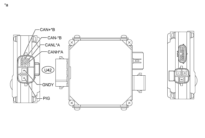
Text in Illustration *A Sub Bus 19 *B Local Bus *a Component without harness connected
(Rear Steering Control ECU)
- -
-
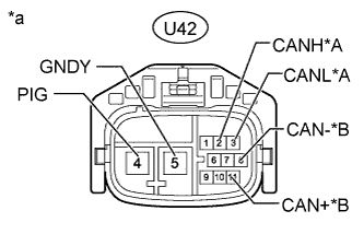
Text in Illustration *A Sub Bus 19 *B Local Bus *a Front view of wire harness connector
(to Rear Steering Control ECU)
Disconnect the rear steering control ECU connector.
-
Measure the resistance according to the value(s) in the table below.
Sub Bus 19 Terminal No. (Symbol) Wiring Color Terminal Description Condition Specified Condition U42-2 (CANH) - U42-3 (CANL) G - SB HIGH-level CAN bus line - LOW-level CAN bus line Cable disconnected from negative (-) battery terminal 54 to 69 Ω U42-2 (CANH) - U42-5 (GNDY) G - W-B HIGH-level CAN bus line - Ground Cable disconnected from negative (-) battery terminal 200 Ω or higher U42-3 (CANL) - U42-5 (GNDY) SB - W-B LOW-level CAN bus line - Ground Cable disconnected from negative (-) battery terminal 200 Ω or higher U42-2 (CANH) - U42-4 (PIG) G - B HIGH-level CAN bus line - Battery positive (+) Cable disconnected from negative (-) battery terminal 6 kΩ or higher U42-3 (CANL) - U42-4 (PIG) SB - B LOW-level CAN bus line - Battery positive (+) Cable disconnected from negative (-) battery terminal 6 kΩ or higher Local Bus Terminal No. (Symbol) Wiring Color Terminal Description Condition Specified Condition U42-11 (CAN+) - U42-8 (CAN-) W - LG HIGH-level CAN bus line - LOW-level CAN bus line Cable disconnected from negative (-) battery terminal 108 to 132 Ω U42-11 (CAN+) - U42-5 (GNDY) W - W-B HIGH-level CAN bus line - Ground Cable disconnected from negative (-) battery terminal 200 Ω or higher U42-8 (CAN-) - U42-5 (GNDY) LG - W-B LOW-level CAN bus line - Ground Cable disconnected from negative (-) battery terminal 200 Ω or higher U42-11 (CAN+) - U42-4 (PIG) W - B HIGH-level CAN bus line - Battery positive (+) Cable disconnected from negative (-) battery terminal 6 kΩ or higher U42-8 (CAN-) - U42-4 (PIG) LG - B LOW-level CAN bus line - Battery positive (+) Cable disconnected from negative (-) battery terminal 6 kΩ or higher
-
-
CHECK FRONT MULTIPLEX NETWORK DOOR ECU LH
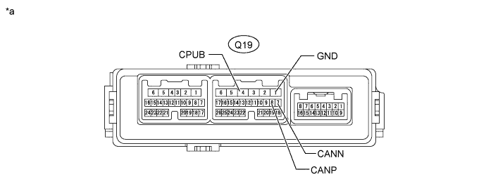
Text in Illustration *a Component without harness connected
(Front Multiplex Network Door ECU LH)
- -
-
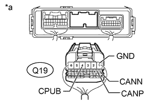
Text in Illustration *a Rear view of wire harness connector
(to Front Multiplex Network Door ECU LH)
Disconnect the front multiplex network door ECU LH connector.
-
Measure the resistance according to the value(s) in the table below.
Terminal No. (Symbol) Wiring Color Terminal Description Condition Specified Condition Q19-8 (CANP) - Q19-7 (CANN) R - G HIGH-level CAN bus line - LOW-level CAN bus line Cable disconnected from negative (-) battery terminal 54 to 69 Ω Q19-8 (CANP) - Q19-1 (GND) R - W-B HIGH-level CAN bus line - Ground Cable disconnected from negative (-) battery terminal 200 Ω or higher Q19-7 (CANN) - Q19-1 (GND) G - W-B LOW-level CAN bus line - Ground Cable disconnected from negative (-) battery terminal 200 Ω or higher Q19-8 (CANP) - Q19-4 (CPUB) R - P HIGH-level CAN bus line - Battery positive (+) Cable disconnected from negative (-) battery terminal 6 kΩ or higher Q19-7 (CANN) - Q19-4 (CPUB) G - P LOW-level CAN bus line - Battery positive (+) Cable disconnected from negative (-) battery terminal 6 kΩ or higher
-
-
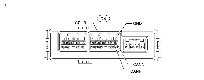
CHECK FRONT MULTIPLEX NETWORK DOOR ECU RH
Text in Illustration *a Component without harness connected
(Front Multiplex Network Door ECU RH)
- -
-
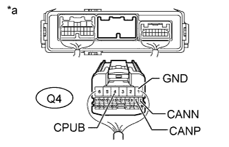
Text in Illustration *a Rear view of wire harness connector
(to Front Multiplex Network Door ECU RH)
Disconnect the front multiplex network door ECU RH connector.
-
Measure the resistance according to the value(s) in the table below.
Terminal No. (Symbol) Wiring Color Terminal Description Condition Specified Condition Q4-8 (CANP) - Q4-7 (CANN) R - G HIGH-level CAN bus line - LOW-level CAN bus line Cable disconnected from negative (-) battery terminal 54 to 69 Ω Q4-8 (CANP) - Q4-1 (GND) R - W-B HIGH-level CAN bus line - Ground Cable disconnected from negative (-) battery terminal 200 Ω or higher Q4-7 (CANN) - Q4-1 (GND) G - W-B LOW-level CAN bus line - Ground Cable disconnected from negative (-) battery terminal 200 Ω or higher Q4-8 (CANP) - Q4-4 (CPUB) R - P HIGH-level CAN bus line - Battery positive (+) Cable disconnected from negative (-) battery terminal 6 kΩ or higher Q4-7 (CANN) - Q4-4 (CPUB) G - P LOW-level CAN bus line - Battery positive (+) Cable disconnected from negative (-) battery terminal 6 kΩ or higher
-
-
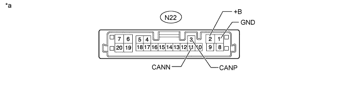
CHECK MULTIPLEX TILT AND TELESCOPIC ECU
Text in Illustration *a Component without harness connected
(Multiplex Tilt and Telescopic ECU)
- -
-
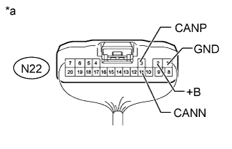
Text in Illustration *a Rear view of wire harness connector
(to Multiplex Tilt and Telescopic ECU)
Disconnect the multiplex tilt and telescopic ECU connector.
-
Measure the resistance according to the value(s) in the table below.
Terminal No. (Symbol) Wiring Color Terminal Description Condition Specified Condition N22-3 (CANP) - N22-11 (CANN) R - GR HIGH-level CAN bus line - LOW-level CAN bus line Cable disconnected from negative (-) battery terminal 54 to 69 Ω N22-3 (CANP) - N22-1 (GND) R - W-B HIGH-level CAN bus line - Ground Cable disconnected from negative (-) battery terminal 200 Ω or higher N22-11 (CANN) - N22-1 (GND) GR - W-B LOW-level CAN bus line - Ground Cable disconnected from negative (-) battery terminal 200 Ω or higher N22-3 (CANP) - N22-2 (+B) R - L HIGH-level CAN bus line - Battery positive (+) Cable disconnected from negative (-) battery terminal 6 kΩ or higher N22-11 (CANN) - N22-2 (+B) GR - L LOW-level CAN bus line - Battery positive (+) Cable disconnected from negative (-) battery terminal 6 kΩ or higher
-
-
CHECK POSITION CONTROL ECU ASSEMBLY LH (except Standard Seat Type)

Text in Illustration *a Component without harness connected
(Position Control ECU Assembly LH)
- -
-
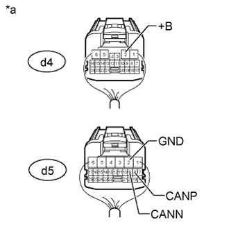
Text in Illustration *a Rear view of wire harness connector
(to Position Control ECU Assembly LH)
Disconnect the position control ECU assembly LH connectors.
-
Measure the resistance according to the value(s) in the table below.
Terminal No. (Symbol) Wiring Color Terminal Description Condition Specified Condition d5-8 (CANP) - d5-9 (CANN) W - R HIGH-level CAN bus line - LOW-level CAN bus line Cable disconnected from negative (-) battery terminal 54 to 69 Ω d5-8 (CANP) - d5-2 (GND) W - B HIGH-level CAN bus line - Ground Cable disconnected from negative (-) battery terminal 200 Ω or higher d5-9 (CANN) - d5-2 (GND) R - B LOW-level CAN bus line - Ground Cable disconnected from negative (-) battery terminal 200 Ω or higher d5-8 (CANP) - d4-2 (+B) W - G HIGH-level CAN bus line - Battery positive (+) Cable disconnected from negative (-) battery terminal 6 kΩ or higher d5-9 (CANN) - d4-2 (+B) R - G LOW-level CAN bus line - Battery positive (+) Cable disconnected from negative (-) battery terminal 6 kΩ or higher
-
-
CHECK POWER SEAT SWITCH ASSEMBLY (for Standard Seat Type)

Text in Illustration *a Component without harness connected
(Power Seat Switch Assembly)
- -
-
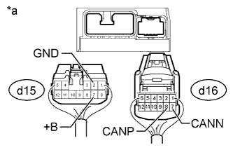
Text in Illustration *a Rear view of wire harness connector
(to Power Seat Switch Assembly)
Disconnect the power seat switch assembly connectors.
-
Measure the resistance according to the value(s) in the table below.
Terminal No. (Symbol) Wiring Color Terminal Description Condition Specified Condition d16-8 (CANP) - d16-7 (CANN) W - R HIGH-level CAN bus line - LOW-level CAN bus line Cable disconnected from negative (-) battery terminal 54 to 69 Ω d16-8 (CANP) - d15-2 (GND) W - B HIGH-level CAN bus line - Ground Cable disconnected from negative (-) battery terminal 200 Ω or higher d16-7 (CANN) - d15-2 (GND) R - B LOW-level CAN bus line - Ground Cable disconnected from negative (-) battery terminal 200 Ω or higher d16-8 (CANP) - d15-7 (+B) W - G HIGH-level CAN bus line - Battery positive (+) Cable disconnected from negative (-) battery terminal 6 kΩ or higher d16-7 (CANN) - d15-7 (+B) R - G LOW-level CAN bus line - Battery positive (+) Cable disconnected from negative (-) battery terminal 6 kΩ or higher
-
-
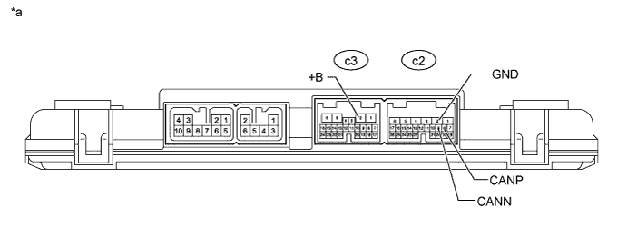
CHECK POSITION CONTROL ECU ASSEMBLY RH (for Luxury Seat Type)
Text in Illustration *a Component without harness connected
(Position Control ECU Assembly RH)
- -
-
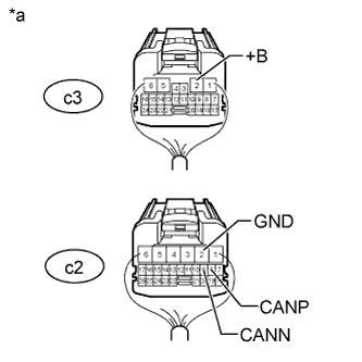
Text in Illustration *a Rear view of wire harness connector
(to Position Control ECU Assembly RH)
Disconnect the position control ECU assembly RH connectors.
-
Measure the resistance according to the value(s) in the table below.
Terminal No. (Symbol) Wiring Color Terminal Description Condition Specified Condition c2-8 (CANP) - c2-9 (CANN) W - R HIGH-level CAN bus line - LOW-level CAN bus line Cable disconnected from negative (-) battery terminal 54 to 69 Ω c2-8 (CANP) - c2-2 (GND) W - B HIGH-level CAN bus line - Ground Cable disconnected from negative (-) battery terminal 200 Ω or higher c2-9 (CANN) - c2-2 (GND) R - B LOW-level CAN bus line - Ground Cable disconnected from negative (-) battery terminal 200 Ω or higher c2-8 (CANP) - c3-2 (+B) W - G HIGH-level CAN bus line - Battery positive (+) Cable disconnected from negative (-) battery terminal 6 kΩ or higher c2-9 (CANN) - c3-2 (+B) R - G LOW-level CAN bus line - Battery positive (+) Cable disconnected from negative (-) battery terminal 6 kΩ or higher
-
-
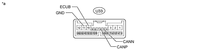
CHECK LUGGAGE CLOSER MOTOR ASSEMBLY (w/ Power Trunk Lid System)
Text in Illustration *a Component without harness connected
(Luggage Closer Motor Assembly)
- -
-
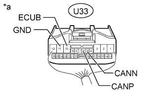
Text in Illustration *a Rear view of wire harness connector
(to Luggage Closer Motor Assembly)
Disconnect the luggage closer motor assembly connector.
-
Measure the resistance according to the value(s) in the table below.
Terminal No. (Symbol) Wiring Color Terminal Description Condition Specified Condition U33-6 (CANP) - U33-5 (CANN) G - GR HIGH-level CAN bus line - LOW-level CAN bus line Cable disconnected from negative (-) battery terminal 54 to 69 Ω U33-6 (CANP) - U33-11 (GND) G - W-B HIGH-level CAN bus line - Ground Cable disconnected from negative (-) battery terminal 200 Ω or higher U33-5 (CANN) - U33-11 (GND) GR - W-B LOW-level CAN bus line - Ground Cable disconnected from negative (-) battery terminal 200 Ω or higher U33-6 (CANP) - U33-10 (ECUB) G - P HIGH-level CAN bus line - Battery positive (+) Cable disconnected from negative (-) battery terminal 6 kΩ or higher U33-5 (CANN) - U33-10 (ECUB) GR - P LOW-level CAN bus line - Battery positive (+) Cable disconnected from negative (-) battery terminal 6 kΩ or higher
-
-
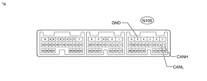
CHECK ABSORBER CONTROL ECU (w/ Adaptive Variable Suspension System)
-
w/o Dynamic Rear Steering System:
Text in Illustration *a Component without harness connected
(Absorber Control ECU)
- -
-
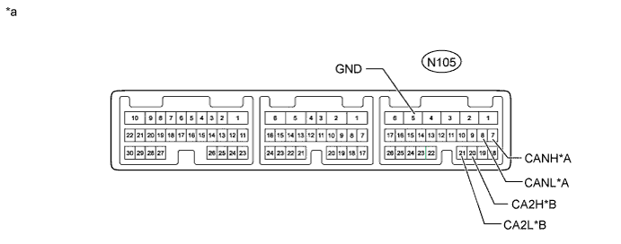
Text in Illustration *a Rear view of wire harness connector
(to Absorber Control ECU)
*b Front view of DLC3 Disconnect the absorber control ECU connector.
-
Measure the resistance according to the value(s) in the table below.
Terminal No. (Symbol) Wiring Color Terminal Description Condition Specified Condition N105-7 (CANH) - N105-8 (CANL) G - LG HIGH-level CAN bus line - LOW-level CAN bus line Cable disconnected from negative (-) battery terminal 54 to 69 Ω N105-7 (CANH) - N105-5 (GND) G - W-B HIGH-level CAN bus line - Ground Cable disconnected from negative (-) battery terminal 200 Ω or higher N105-8 (CANL) - N105-5 (GND) LG - W-B LOW-level CAN bus line - Ground Cable disconnected from negative (-) battery terminal 200 Ω or higher N105-7 (CANH) - N20-16 (BAT) G - Y HIGH-level CAN bus line - Battery positive (+) Cable disconnected from negative (-) battery terminal 6 kΩ or higher N105-8 (CANL) - N20-16 (BAT) LG - Y LOW-level CAN bus line - Battery positive (+) Cable disconnected from negative (-) battery terminal 6 kΩ or higher
-
-
w/ Dynamic Rear Steering System:
Text in Illustration *A Sub Bus 18 *B Sub Bus 19 *a Component without harness connected
(Absorber Control ECU)
- -
-
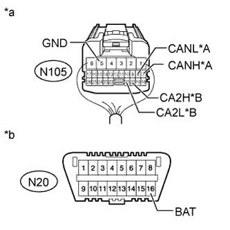
Text in Illustration *A Sub Bus 18 *B Sub Bus 19 *a Rear view of wire harness connector
(to Absorber Control ECU)
*b Front view of DLC3 Disconnect the absorber control ECU connector.
-
Measure the resistance according to the value(s) in the table below.
Sub Bus 18 Terminal No. (Symbol) Wiring Color Terminal Description Condition Specified Condition N105-7 (CANH) - N105-8 (CANL) G - LG HIGH-level CAN bus line - LOW-level CAN bus line Cable disconnected from negative (-) battery terminal 54 to 69 Ω N105-7 (CANH) - N105-5 (GND) G - W-B HIGH-level CAN bus line - Ground Cable disconnected from negative (-) battery terminal 200 Ω or higher N105-8 (CANL) - N105-5 (GND) LG - W-B LOW-level CAN bus line - Ground Cable disconnected from negative (-) battery terminal 200 Ω or higher N105-7 (CANH) - N20-16 (BAT) G - Y HIGH-level CAN bus line - Battery positive (+) Cable disconnected from negative (-) battery terminal 6 kΩ or higher N105-8 (CANL) - N20-16 (BAT) LG - Y LOW-level CAN bus line - Battery positive (+) Cable disconnected from negative (-) battery terminal 6 kΩ or higher Sub Bus 19 Terminal No. (Symbol) Wiring Color Terminal Description Condition Specified Condition N105-20 (CA2H) - N105-21 (CA2L) L - SB HIGH-level CAN bus line - LOW-level CAN bus line Cable disconnected from negative (-) battery terminal 54 to 69 Ω N105-20 (CA2H) - N105-5 (GND) L - W-B HIGH-level CAN bus line - Ground Cable disconnected from negative (-) battery terminal 200 Ω or higher N105-21 (CA2L) - N105-5 (GND) SB - W-B LOW-level CAN bus line - Ground Cable disconnected from negative (-) battery terminal 200 Ω or higher N105-20 (CA2H) - N20-16 (BAT) L - Y HIGH-level CAN bus line - Battery positive (+) Cable disconnected from negative (-) battery terminal 6 kΩ or higher N105-21 (CA2L) - N20-16 (BAT) SB - Y LOW-level CAN bus line - Battery positive (+) Cable disconnected from negative (-) battery terminal 6 kΩ or higher
-
-
-
CHECK 4WD ECU ASSEMBLY (for AWD)
Text in Illustration *a Component without harness connected
(4WD ECU Assembly)
- -
-
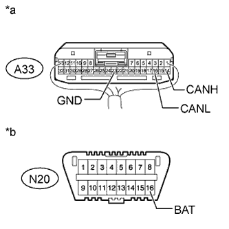
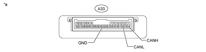
Text in Illustration *a Rear view of wire harness connector
(to 4WD ECU Assembly)
*b Front view of DLC3 Disconnect the 4WD ECU assembly connector.
-
Measure the resistance according to the value(s) in the table below.
Terminal No. (Symbol) Wiring Color Terminal Description Condition Specified Condition A33-14 (CANH) - A33-16 (CANL) V - LG HIGH-level CAN bus line - LOW-level CAN bus line Cable disconnected from negative (-) battery terminal 54 to 69 Ω A33-14 (CANH) - A33-23 (GND) V - W-B HIGH-level CAN bus line - Ground Cable disconnected from negative (-) battery terminal 200 Ω or higher A33-16 (CANL) - A33-23 (GND) LG - W-B LOW-level CAN bus line - Ground Cable disconnected from negative (-) battery terminal 200 Ω or higher A33-14 (CANH) - N20-16 (BAT) V - Y HIGH-level CAN bus line - Battery positive (+) Cable disconnected from negative (-) battery terminal 6 kΩ or higher A33-16 (CANL) - N20-16 (BAT) LG - Y LOW-level CAN bus line - Battery positive (+) Cable disconnected from negative (-) battery terminal 6 kΩ or higher
-
-
CHECK CLEARANCE WARNING ECU ASSEMBLY (w/ LEXUS Parking Assist-sensor System)
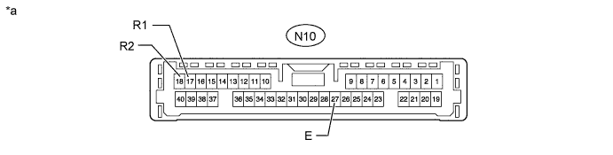
Text in Illustration *a Component without harness connected
(Clearance Warning ECU Assembly)
- -
-
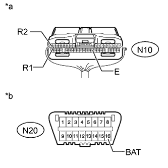
Text in Illustration *a Rear view of wire harness connector
(to Clearance Warning ECU Assembly)
*b Front view of DLC3 Disconnect the clearance warning ECU assembly connector.
-
Measure the resistance according to the value(s) in the table below.
Terminal No. (Symbol) Wiring Color Terminal Description Condition Specified Condition N10-17 (R1) - N10-18 (R2) L - LG HIGH-level CAN bus line - LOW-level CAN bus line Cable disconnected from negative (-) battery terminal 54 to 69 Ω N10-17 (R1) - N10-27 (E) L - W-B HIGH-level CAN bus line - Ground Cable disconnected from negative (-) battery terminal 200 Ω or higher N10-18 (R2) - N10-27 (E) LG - W-B LOW-level CAN bus line - Ground Cable disconnected from negative (-) battery terminal 200 Ω or higher N10-17 (R1) - N20-16 (BAT) L - Y HIGH-level CAN bus line - Battery positive (+) Cable disconnected from negative (-) battery terminal 6 kΩ or higher N10-18 (R2) - N20-16 (BAT) LG - Y LOW-level CAN bus line - Battery positive (+) Cable disconnected from negative (-) battery terminal 6 kΩ or higher
-
-
CHECK BLIND SPOT MONITOR SENSOR RH (w/ Blind Spot Monitor System)
-
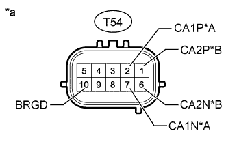
Text in Illustration *A Sub Bus 2 *B Sensor Bus *a Component without harness connected
(Blind Spot Monitor Sensor RH)
w/o Dynamic Rear Steering System:
-
Disconnect the blind spot monitor sensor RH connector.
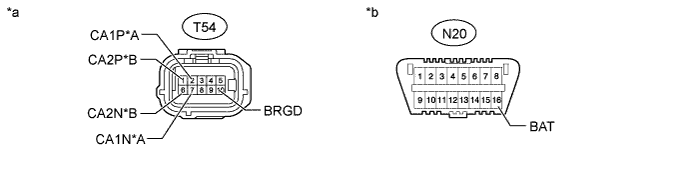
Text in Illustration *A Sub Bus 2 *B Sensor Bus *a Front view of wire harness connector
(to Blind Spot Monitor Sensor RH)
*b Front view of DLC3 -
Measure the resistance according to the value(s) in the table below.
Sub Bus 2 Terminal No. (Symbol) Wiring Color Terminal Description Condition Specified Condition T54-2 (CA1P) - T54-7 (CA1N) L - LG HIGH-level CAN bus line - LOW-level CAN bus line Cable disconnected from negative (-) battery terminal 54 to 69 Ω T54-2 (CA1P) - T54-10 (BRGD) L - W-B HIGH-level CAN bus line - Ground Cable disconnected from negative (-) battery terminal 200 Ω or higher T54-7 (CA1N) - T54-10 (BRGD) LG - W-B LOW-level CAN bus line - Ground Cable disconnected from negative (-) battery terminal 200 Ω or higher T54-2 (CA1P) - N20-16 (BAT) L - Y HIGH-level CAN bus line - Battery positive (+) Cable disconnected from negative (-) battery terminal 6 kΩ or higher T54-7 (CA1N) - N20-16 (BAT) LG - Y LOW-level CAN bus line - Battery positive (+) Cable disconnected from negative (-) battery terminal 6 kΩ or higher Sensor Bus Terminal No. (Symbol) Wiring Color Terminal Description Condition Specified Condition T54-1 (CA2P) - T54-6 (CA2N) W - Y HIGH-level CAN bus line - LOW-level CAN bus line Cable disconnected from negative (-) battery terminal 108 to 132 Ω T54-1 (CA2P) - T54-10 (BRGD) W - W-B LOW-level CAN bus line - Ground Cable disconnected from negative (-) battery terminal 200 Ω or higher T54-6 (CA2N) - T54-10 (BRGD) Y - W-B LOW-level CAN bus line - Ground Cable disconnected from negative (-) battery terminal 200 Ω or higher T54-1 (CA2P) - N20-16 (BAT) W - Y HIGH-level CAN bus line - Battery positive (+) Cable disconnected from negative (-) battery terminal 6 kΩ or higher T54-6 (CA2N) - N20-16 (BAT) Y - Y LOW-level CAN bus line - Battery positive (+) Cable disconnected from negative (-) battery terminal 6 kΩ or higher
-
-
Text in Illustration *A Sub Bus 18 *B Sensor Bus *a Component without harness connected
(Blind Spot Monitor Sensor RH)
w/ Dynamic Rear Steering System:
-
Disconnect the blind spot monitor sensor RH connector.
Text in Illustration *A Sub Bus 18 *B Sensor Bus *a Front view of wire harness connector
(to Blind Spot Monitor Sensor RH)
*b Front view of DLC3 -
Measure the resistance according to the value(s) in the table below.
Sub Bus 18 Terminal No. (Symbol) Wiring Color Terminal Description Condition Specified Condition T54-2 (CA1P) - T54-7 (CA1N) L - LG HIGH-level CAN bus line - LOW-level CAN bus line Cable disconnected from negative (-) battery terminal 54 to 69 Ω T54-2 (CA1P) - T54-10 (BRGD) L - W-B HIGH-level CAN bus line - Ground Cable disconnected from negative (-) battery terminal 200 Ω or higher T54-7 (CA1N) - T54-10 (BRGD) LG - W-B LOW-level CAN bus line - Ground Cable disconnected from negative (-) battery terminal 200 Ω or higher T54-2 (CA1P) - N20-16 (BAT) L - Y HIGH-level CAN bus line - Battery positive (+) Cable disconnected from negative (-) battery terminal 6 kΩ or higher T54-7 (CA1N) - N20-16 (BAT) LG - Y LOW-level CAN bus line - Battery positive (+) Cable disconnected from negative (-) battery terminal 6 kΩ or higher Sensor Bus Terminal No. (Symbol) Wiring Color Terminal Description Condition Specified Condition T54-1 (CA2P) - T54-6 (CA2N) W - Y HIGH-level CAN bus line - LOW-level CAN bus line Cable disconnected from negative (-) battery terminal 108 to 132 Ω T54-1 (CA2P) - T54-10 (BRGD) W - W-B LOW-level CAN bus line - Ground Cable disconnected from negative (-) battery terminal 200 Ω or higher T54-6 (CA2N) - T54-10 (BRGD) Y - W-B LOW-level CAN bus line - Ground Cable disconnected from negative (-) battery terminal 200 Ω or higher T54-1 (CA2P) - N20-16 (BAT) W - Y HIGH-level CAN bus line - Battery positive (+) Cable disconnected from negative (-) battery terminal 6 kΩ or higher T54-6 (CA2N) - N20-16 (BAT) Y - Y LOW-level CAN bus line - Battery positive (+) Cable disconnected from negative (-) battery terminal 6 kΩ or higher
-
-
-
CHECK BLIND SPOT MONITOR SENSOR LH (w/ Blind Spot Monitor System)
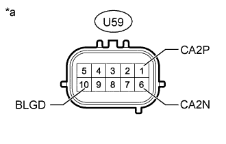
Text in Illustration *a Component without harness connected
(Blind Spot Monitor Sensor LH)
-
Disconnect the blind spot monitor sensor LH connector.
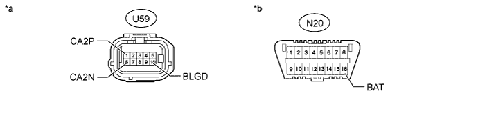
Text in Illustration *a Front view of wire harness connector
(to Blind Spot Monitor Sensor LH)
*b Front view of DLC3 -
Measure the resistance according to the value(s) in the table below.
Terminal No. (Symbol) Wiring Color Terminal Description Condition Specified Condition U59-1 (CA2P) - U59-6 (CA2N) W - Y HIGH-level CAN bus line - LOW-level CAN bus line Cable disconnected from negative (-) battery terminal 108 to 132 Ω U59-1 (CA2P) - U59-10 (BLGD) W - W-B HIGH-level CAN bus line - Ground Cable disconnected from negative (-) battery terminal 200 Ω or higher U59-6 (CA2N) - U59-10 (BLGD) Y - W-B LOW-level CAN bus line - Ground Cable disconnected from negative (-) battery terminal 200 Ω or higher U59-1 (CA2P) - N20-16 (BAT) W - Y HIGH-level CAN bus line - Battery positive (+) Cable disconnected from negative (-) battery terminal 6 kΩ or higher U59-6 (CA2N) - N20-16 (BAT) Y - Y LOW-level CAN bus line - Battery positive (+) Cable disconnected from negative (-) battery terminal 6 kΩ or higher
-
-
CHECK SEAT BELT CONTROL ECU (w/ Pre-crash Safety System)
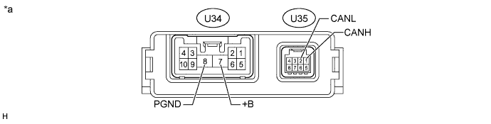
Text in Illustration *a Component without harness connected
(Seat Belt Control ECU)
- -
-
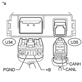
Text in Illustration *a Rear view of wire harness connector
(to Seat Belt Control ECU)
Disconnect the seat belt control ECU connectors.
-
Measure the resistance according to the value(s) in the table below.
Terminal No. (Symbol) Wiring Color Terminal Description Condition Specified Condition U35-1 (CANH) - U35-2 (CANL) Y - LG HIGH-level CAN bus line - LOW-level CAN bus line Cable disconnected from negative (-) battery terminal 54 to 69 Ω U35-1 (CANH) - U34-8 (PGND) Y - W-B HIGH-level CAN bus line - Ground Cable disconnected from negative (-) battery terminal 200 Ω or higher U35-2 (CANL) - U34-8 (PGND) LG - W-B LOW-level CAN bus line - Ground Cable disconnected from negative (-) battery terminal 200 Ω or higher U35-1 (CANH) - U34-7 (+B) Y - R HIGH-level CAN bus line - Battery positive (+) Cable disconnected from negative (-) battery terminal 6 kΩ or higher U35-2 (CANL) - U34-7 (+B) LG - R LOW-level CAN bus line - Battery positive (+) Cable disconnected from negative (-) battery terminal 6 kΩ or higher
-
-
CHECK DRIVING SUPPORT ECU ASSEMBLY (w/ Dynamic Radar Cruise Control System)
Note
If a load of more than 10 kg (22 lb.) is placed on the connector, it may break. Do not place more load than is necessary on the connector.
-
w/o Dynamic Rear Steering System:
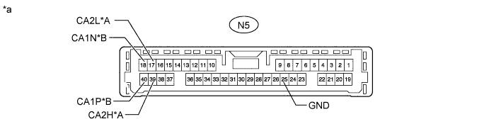
Text in Illustration *A Sub Bus 2 *B Sub Bus 13 *a Component without harness connected
(Driving Support ECU Assembly)
- -
-
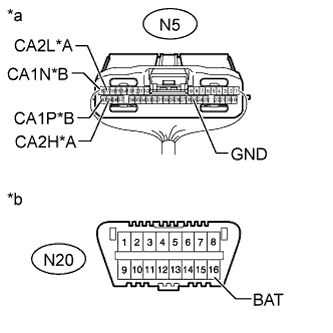
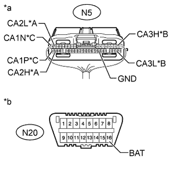
Text in Illustration *A Sub Bus 2 *B Sub Bus 13 *a Rear view of wire harness connector
(to Driving Support ECU Assembly)
*b Front view of DLC3 Disconnect the driving support ECU assembly connector.
-
Measure the resistance according to the value(s) in the table below.
Sub Bus 2 Terminal No. (Symbol) Wiring Color Terminal Description Condition Specified Condition N5-39 (CA2H) - N5-17 (CA2L) V - LG HIGH-level CAN bus line - LOW-level CAN bus line Cable disconnected from negative (-) battery terminal 54 to 69 Ω N5-39 (CA2H) - N5-25 (GND) V - BR HIGH-level CAN bus line - Ground Cable disconnected from negative (-) battery terminal 200 Ω or higher N5-17 (CA2L) - N5-25 (GND) LG - BR LOW-level CAN bus line - Ground Cable disconnected from negative (-) battery terminal 200 Ω or higher N5-39 (CA2H) - N20-16 (BAT) V - Y HIGH-level CAN bus line - Battery positive (+) Cable disconnected from negative (-) battery terminal 6 kΩ or higher N5-17 (CA2L) - N20-16 (BAT) LG - Y LOW-level CAN bus line - Battery positive (+) Cable disconnected from negative (-) battery terminal 6 kΩ or higher Sub Bus 13 Terminal No. (Symbol) Wiring Color Terminal Description Condition Specified Condition N5-40 (CA1P) - N5-18 (CA1N) G - W HIGH-level CAN bus line - LOW-level CAN bus line Cable disconnected from negative (-) battery terminal 54 to 69 Ω N5-40 (CA1P) - N5-25 (GND) G - BR HIGH-level CAN bus line - Ground Cable disconnected from negative (-) battery terminal 200 Ω or higher N5-18 (CA1N) - N5-25 (GND) W - BR LOW-level CAN bus line - Ground Cable disconnected from negative (-) battery terminal 200 Ω or higher N5-40 (CA1P) - N20-16 (BAT) G - Y HIGH-level CAN bus line - Battery positive (+) Cable disconnected from negative (-) battery terminal 6 kΩ or higher N5-18 (CA1N) - N20-16 (BAT) W - Y LOW-level CAN bus line - Battery positive (+) Cable disconnected from negative (-) battery terminal 6 kΩ or higher
-
-
w/ Dynamic Rear Steering System:
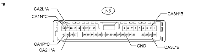
Text in Illustration *A Sub Bus 18 *B Sub Bus 19 *C Sub Bus 13 - - *a Component without harness connected
(Driving Support ECU Assembly)
- -
-
Text in Illustration *A Sub Bus 18 *B Sub Bus 19 *C Sub Bus 13 *a Rear view of wire harness connector
(to Driving Support ECU Assembly)
*b Front view of DLC3 Disconnect the driving support ECU assembly connector.
-
Measure the resistance according to the value(s) in the table below.
Sub Bus 18 Terminal No. (Symbol) Wiring Color Terminal Description Condition Specified Condition N5-39 (CA2H) - N5-17 (CA2L) V - LG HIGH-level CAN bus line - LOW-level CAN bus line Cable disconnected from negative (-) battery terminal 54 to 69 Ω N5-39 (CA2H) - N5-25 (GND) V - BR HIGH-level CAN bus line - Ground Cable disconnected from negative (-) battery terminal 200 Ω or higher N5-17 (CA2L) - N5-25 (GND) LG - BR LOW-level CAN bus line - Ground Cable disconnected from negative (-) battery terminal 200 Ω or higher N5-39 (CA2H) - N20-16 (BAT) V - Y HIGH-level CAN bus line - Battery positive (+) Cable disconnected from negative (-) battery terminal 6 kΩ or higher N5-17 (CA2L) - N20-16 (BAT) LG - Y LOW-level CAN bus line - Battery positive (+) Cable disconnected from negative (-) battery terminal 6 kΩ or higher Sub Bus 19 Terminal No. (Symbol) Wiring Color Terminal Description Condition Specified Condition N5-2 (CA3H) - N5-20 (CA3L) G - SB HIGH-level CAN bus line - LOW-level CAN bus line Cable disconnected from negative (-) battery terminal 54 to 69 Ω N5-2 (CA3H) - N5-25 (GND) G - BR HIGH-level CAN bus line - Ground Cable disconnected from negative (-) battery terminal 200 Ω or higher N5-20 (CA3L) - N5-25 (GND) SB - BR LOW-level CAN bus line - Ground Cable disconnected from negative (-) battery terminal 200 Ω or higher N5-2 (CA3H) - N20-16 (BAT) G - Y HIGH-level CAN bus line - Battery positive (+) Cable disconnected from negative (-) battery terminal 6 kΩ or higher N5-20 (CA3L) - N20-16 (BAT) SB - Y LOW-level CAN bus line - Battery positive (+) Cable disconnected from negative (-) battery terminal 6 kΩ or higher Sub Bus 13 Terminal No. (Symbol) Wiring Color Terminal Description Condition Specified Condition N5-40 (CA1P) - N5-18 (CA1N) G - W HIGH-level CAN bus line - LOW-level CAN bus line Cable disconnected from negative (-) battery terminal 54 to 69 Ω N5-40 (CA1P) - N5-25 (GND) G - BR HIGH-level CAN bus line - Ground Cable disconnected from negative (-) battery terminal 200 Ω or higher N5-18 (CA1N) - N5-25 (GND) W - BR LOW-level CAN bus line - Ground Cable disconnected from negative (-) battery terminal 200 Ω or higher N5-40 (CA1P) - N20-16 (BAT) G - Y HIGH-level CAN bus line - Battery positive (+) Cable disconnected from negative (-) battery terminal 6 kΩ or higher N5-18 (CA1N) - N20-16 (BAT) W - Y LOW-level CAN bus line - Battery positive (+) Cable disconnected from negative (-) battery terminal 6 kΩ or higher
-
-
-
CHECK MILLIMETER WAVE RADAR SENSOR ASSEMBLY (w/ Dynamic Radar Cruise Control System)
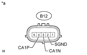
Text in Illustration *a Component without harness connected
(Millimeter Wave Radar Sensor Assembly)
-
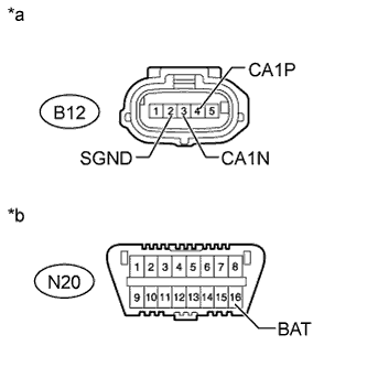
Text in Illustration *a Front view of wire harness connector
(to Millimeter Wave Radar Sensor Assembly)
*b Front view of DLC3 Disconnect the millimeter wave radar sensor assembly connector.
-
Measure the resistance according to the value(s) in the table below.
Terminal No. (Symbol) Wiring Color Terminal Description Condition Specified Condition B12-4 (CA1P) - B12-3 (CA1N) W - B HIGH-level CAN bus line - LOW-level CAN bus line Cable disconnected from negative (-) battery terminal 108 to 132 Ω B12-4 (CA1P) - B12-2 (SGND) W - BR HIGH-level CAN bus line - Ground Cable disconnected from negative (-) battery terminal 200 Ω or higher B12-3 (CA1N) - B12-2 (SGND) B - BR LOW-level CAN bus line - Ground Cable disconnected from negative (-) battery terminal 200 Ω or higher B12-4 (CA1P) - N20-16 (BAT) W - Y HIGH-level CAN bus line - Battery positive (+) Cable disconnected from negative (-) battery terminal 6 kΩ or higher B12-3 (CA1N) - N20-16 (BAT) B - Y LOW-level CAN bus line - Battery positive (+) Cable disconnected from negative (-) battery terminal 6 kΩ or higher
-
-
CHECK DRIVER MONITOR ECU ASSEMBLY (w/ Driver Monitor Camera)
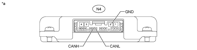
Text in Illustration *a Component without harness connected
(Driver Monitor ECU Assembly)
- -
-
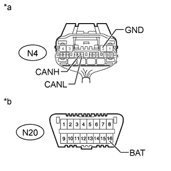
Text in Illustration *a Rear view of wire harness connector
(to Driver Monitor ECU Assembly)
*b Front view of DLC3 Disconnect the driver monitor ECU assembly connector.
-
Measure the resistance according to the value(s) in the table below.
Terminal No. (Symbol) Wiring Color Terminal Description Condition Specified Condition N4-12 (CANH) - N4-11 (CANL) R - W HIGH-level CAN bus line - LOW-level CAN bus line Cable disconnected from negative (-) battery terminal 54 to 69 Ω N4-12 (CANH) - N4-2 (GND) R - W-B HIGH-level CAN bus line - Ground Cable disconnected from negative (-) battery terminal 200 Ω or higher N4-11 (CANL) - N4-2 (GND) W - W-B LOW-level CAN bus line - Ground Cable disconnected from negative (-) battery terminal 200 Ω or higher N4-12 (CANH) - N20-16 (BAT) R - Y HIGH-level CAN bus line - Battery positive (+) Cable disconnected from negative (-) battery terminal 6 kΩ or higher N4-11 (CANL) - N20-16 (BAT) W - Y LOW-level CAN bus line - Battery positive (+) Cable disconnected from negative (-) battery terminal 6 kΩ or higher
-
-
CHECK LANE RECOGNITION CAMERA SENSOR ASSEMBLY (w/ Lane-keeping Assist System)
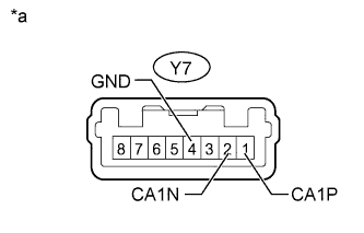
Text in Illustration *a Component without harness connected
(to Lane Recognition Camera Sensor Assembly)
-
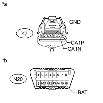
Text in Illustration *a Rear view of wire harness connector
(to Lane Recognition Camera Sensor Assembly)
*b Front view of DLC3 Disconnect the lane recognition camera sensor assembly connector.
-
Measure the resistance according to the value(s) in the table below.
Terminal No. (Symbol) Wiring Color Terminal Description Condition Specified Condition Y7-1 (CA1P) - Y7-2 (CA1N) W - B HIGH-level CAN bus line - LOW-level CAN bus line Cable disconnected from negative (-) battery terminal 54 to 69 Ω Y7-1 (CA1P) - Y7-4 (GND) W - BR HIGH-level CAN bus line - Ground Cable disconnected from negative (-) battery terminal 200 Ω or higher Y7-2 (CA1N) - Y7-4 (GND) B - BR LOW-level CAN bus line - Ground Cable disconnected from negative (-) battery terminal 200 Ω or higher Y7-1 (CA1P) - N20-16 (BAT) W - Y HIGH-level CAN bus line - Battery positive (+) Cable disconnected from negative (-) battery terminal 6 kΩ or higher Y7-2 (CA1N) - N20-16 (BAT) B - Y LOW-level CAN bus line - Battery positive (+) Cable disconnected from negative (-) battery terminal 6 kΩ or higher
-
-
CHECK NO. 1 NIGHT VIEW ECU (w/ Night View System)
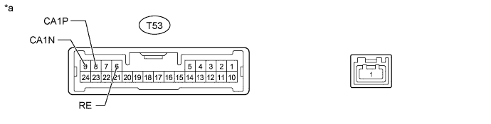
Text in Illustration *a Component without harness connected
(No. 1 Night View ECU)
- -
-
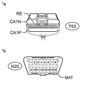
Text in Illustration *a Rear view of wire harness connector
(to No. 1 Night View ECU)
*b Front view of DLC3 Disconnect the No. 1 night view ECU connector.
-
Measure the resistance according to the value(s) in the table below.
Terminal No. (Symbol) Wiring Color Terminal Description Condition Specified Condition T53-8 (CA1P) - T53-9 (CA1N) G - W HIGH-level CAN bus line - LOW-level CAN bus line Cable disconnected from negative (-) battery terminal 54 to 69 Ω T53-8 (CA1P) - T53-6 (RE) G - W-B HIGH-level CAN bus line - Ground Cable disconnected from negative (-) battery terminal 200 Ω or higher T53-9 (CA1N) - T53-6 (RE) W - W-B LOW-level CAN bus line - Ground Cable disconnected from negative (-) battery terminal 200 Ω or higher T53-8 (CA1P) - N20-16 (BAT) G - Y HIGH-level CAN bus line - Battery positive (+) Cable disconnected from negative (-) battery terminal 6 kΩ or higher T53-9 (CA1N) - N20-16 (BAT) W - Y LOW-level CAN bus line - Battery positive (+) Cable disconnected from negative (-) battery terminal 6 kΩ or higher
-
-
CHECK TRANSMISSION CONTROL ECU ASSEMBLY (for AA81E)
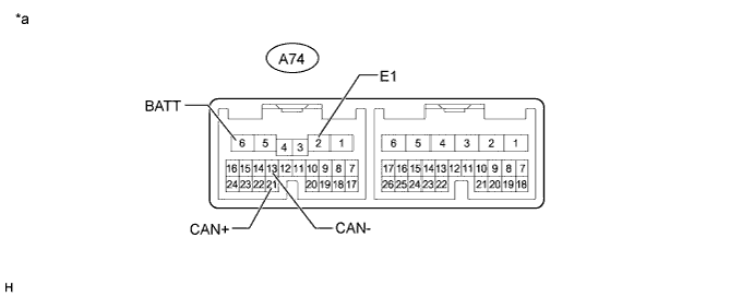
Text in Illustration *a Component without harness connected
(Transmission Control ECU Assembly)
- -
-
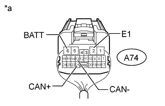
Text in Illustration *a Rear view of wire harness connector
(to Transmission Control ECU Assembly)
Disconnect the transmission control ECU assembly connector.
-
Measure the resistance according to the value(s) in the table below.
Terminal No. (Symbol) Wiring Color Terminal Description Condition Specified Condition A74-21 (CAN+) - A74-13 (CAN-) R - L HIGH-level CAN bus line - LOW-level CAN bus line Cable disconnected from negative (-) battery terminal 108 to 132 Ω A74-21 (CAN+) - A74-2 (E1) R - W-B HIGH-level CAN bus line - Ground Cable disconnected from negative (-) battery terminal 200 Ω or higher A74-13 (CAN-) - A74-2 (E1) L - W-B LOW-level CAN bus line - Ground Cable disconnected from negative (-) battery terminal 200 Ω or higher A74-21 (CAN+) - A74-6 (BATT) R - L HIGH-level CAN bus line - Battery positive (+) Cable disconnected from negative (-) battery terminal 6 kΩ or higher A74-13 (CAN-) - A74-6 (BATT) L - L LOW-level CAN bus line - Battery positive (+) Cable disconnected from negative (-) battery terminal 6 kΩ or higher
-
-
CHECK TELEMATICS TRANSCEIVER (w/ TELEMATICS TRANSCEIVER)
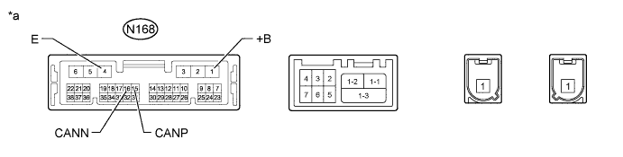
Text in Illustration *a Component without harness connected
(Telematics Transceiver)
- -
-
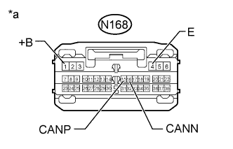
Text in Illustration *a Front view of wire harness connector
(to Telematics Transceiver)
Disconnect the telematics transceiver connector.
-
Measure the resistance according to the value(s) in the table below.
Terminal No. (Symbol) Wiring Color Terminal Description Condition Specified Condition N168-15 (CANP) - N168-16 (CANN) W - LG HIGH-level CAN bus line - LOW-level CAN bus line Cable disconnected from negative (-) battery terminal 54 to 69 Ω N168-15 (CANP) - N168-4 (E) W - W-B HIGH-level CAN bus line - Ground Cable disconnected from negative (-) battery terminal 200 Ω or higher N168-16 (CANN) - N168-4 (E) LG - W-B LOW-level CAN bus line - Ground Cable disconnected from negative (-) battery terminal 200 Ω or higher N168-15 (CANP) - N168-1 (+B) W - GR HIGH-level CAN bus line - Battery positive (+) Cable disconnected from negative (-) battery terminal 6 kΩ or higher N168-16 (CANN) - N168-1 (+B) LG - GR LOW-level CAN bus line - Battery positive (+) Cable disconnected from negative (-) battery terminal 6 kΩ or higher
-