CAN COMMUNICATION SYSTEM (for LHD) SYSTEM DIAGRAM

-
SYSTEM DIAGRAM (w/o Dynamic Rear Steering System)
-
Overall CAN Bus Diagram
-
Control system CAN is composed of 7 buses.
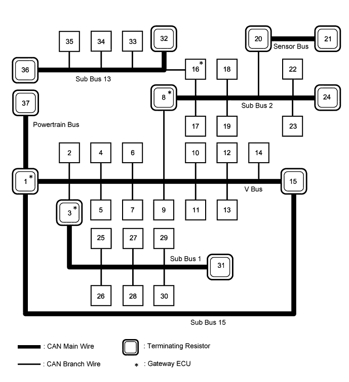
No. ECU/Sensor Name 1 ECM 2 Parking brake ECU assembly 3 Main body ECU (multiplex network body ECU) 4 Brake actuator assembly (skid control ECU) 5 Combination meter assembly 6 DLC3 7 Headlight swivel ECU assembly (AFS ECU) 8 Network gateway ECU*1 9 Air conditioning amplifier assembly 10 Spiral with sensor cable sub-assembly (steering angle sensor) 11 Yaw rate sensor 12 Multi-media module receiver assembly 13 Power steering ECU assembly 14 Center airbag sensor assembly 15 Certification ECU (smart key ECU assembly) 16 Driving support ECU assembly*2 17 Absorber control ECU*3 18 4WD ECU assembly*4 19 Clearance warning ECU assembly*5 20 Blind spot monitor sensor RH*6 21 Blind spot monitor sensor LH*6 22 Seat belt control ECU*7 23 Telematics transceiver*16 24 No. 9 junction connector 25 Luggage closer motor assembly*8 26 Front multiplex network door ECU LH 27 Front multiplex network door ECU RH 28 Multiplex tilt and telescopic ECU 29
-
Position control ECU assembly LH*9
-
Power seat switch assembly*10
30 Position control ECU assembly RH*11 31 No. 11 junction connector 32 Millimeter wave radar sensor assembly*2 33 Lane recognition camera sensor assembly*12 34 Driver monitor ECU assembly*13 35 No.1 night view ECU*14 36 No. 12 junction connector 37 Transmission control ECU assembly*15
-
*1: w/ Network Gateway ECU
-
*2: w/ Dynamic Radar Cruise Control System
-
*3: w/ Adaptive Variable Suspension System
-
*4: for AWD
-
*5: w/ LEXUS Parking Assist-sensor System
-
*6: w/ Blind Spot Monitor System
-
*7: w/ Pre-crash Safety System
-
*8: w/ Power Trunk Lid System
-
*9: except Standard Seat Type
-
*10: for Standard Seat Type
-
*11: for Luxury Seat Type
-
*12: w/ Lane-keeping Assist System
-
*13: w/ Driver Monitor Camera
-
*14: w/ Night View System
-
*15: for AA81E
-
*16: w/ Telematics Transceiver
Tech Tips
-
The network gateway ECU functions as a gateway between the V bus and sub bus 2.
-
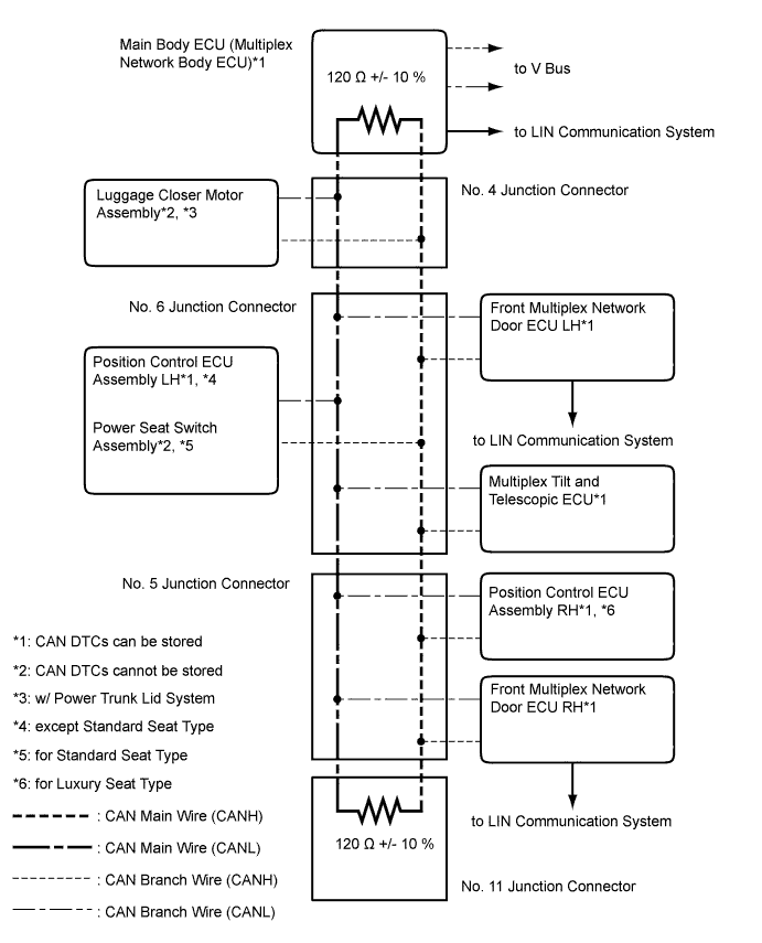
The main body ECU (multiplex network body ECU) functions as a gateway between the V bus and sub bus 1.
-
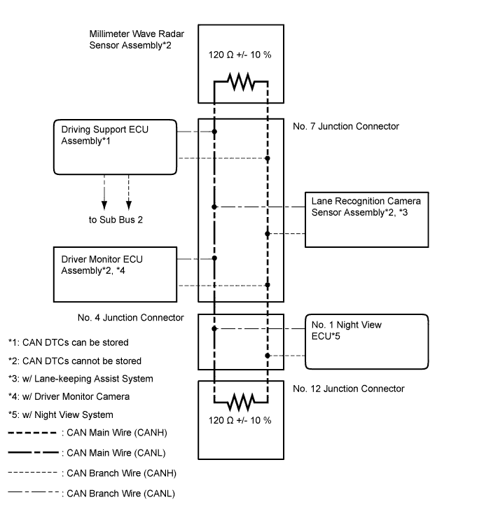
The driving support ECU assembly functions as a gateway between the sub bus 2 and sub bus 13.
-
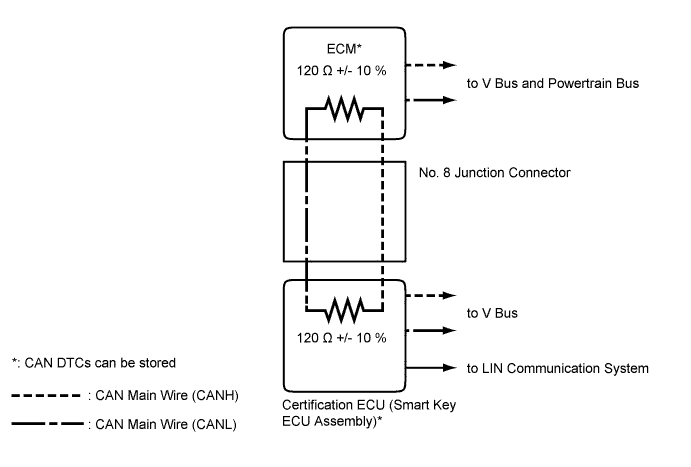
The certification ECU (smart key ECU assembly) functions as a gateway between the V bus and sub bus 15.
-
Refer to the following bus wiring diagrams for details.
-
-
-
V Bus
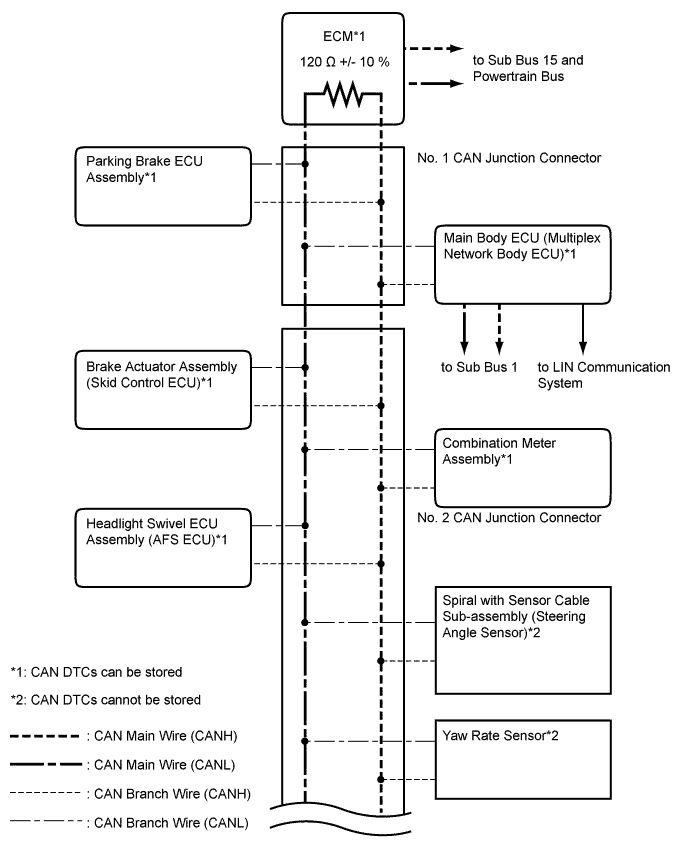
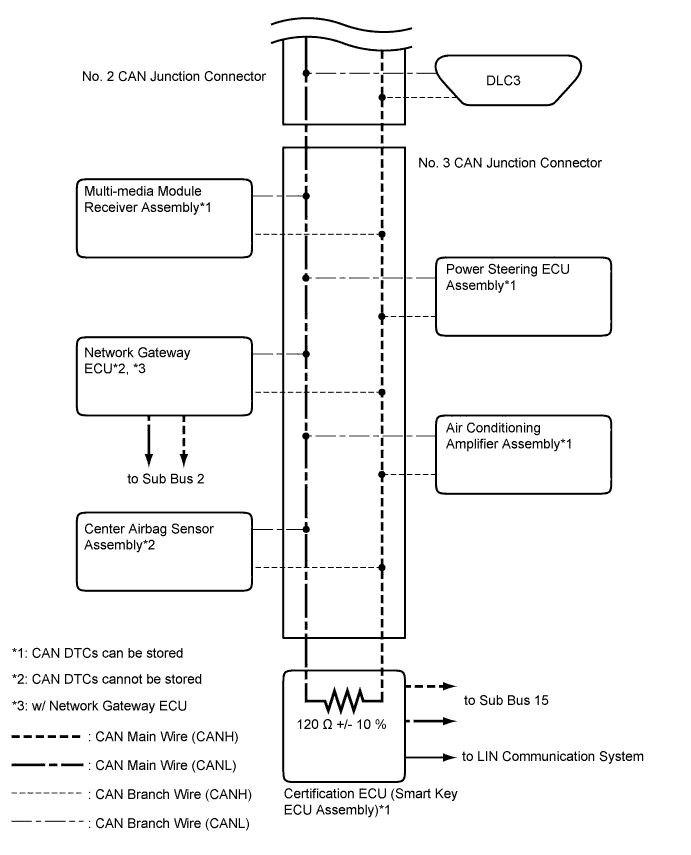
Tech Tips
The CAN communication system connects to other networks via ECUs that function as a gateway Click here.
-
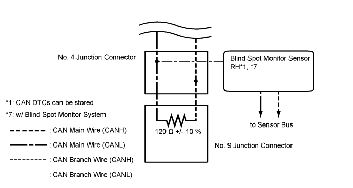
Sub Bus 2 (w/ Network Gateway ECU)
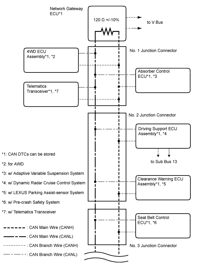
-
Sub Bus 1
Tech Tips
The CAN communication system connects to other networks via ECUs that function as a gateway Click here.
-
Sub Bus 13 (w/ Dynamic Radar Cruise Control System)
-
Sub Bus 15
Tech Tips
The CAN communication system connects to other networks via ECUs that function as a gateway Click here.
-
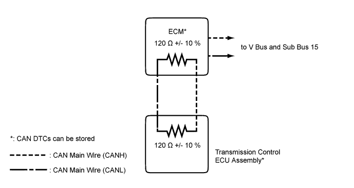
Powertrain Bus (for AA81E)
-
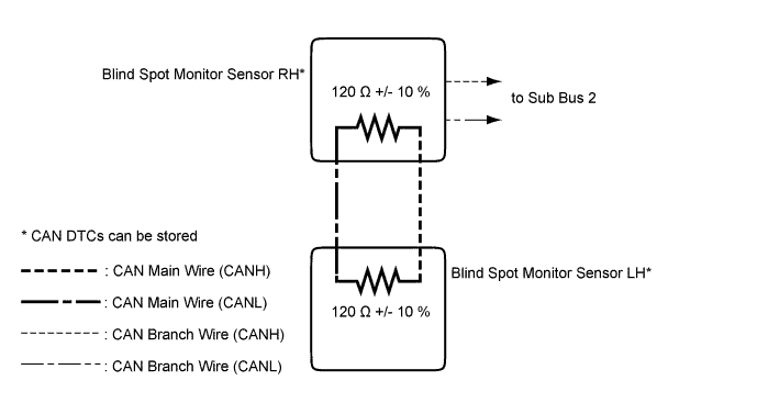
Sensor Bus (w/ Blind Spot Monitor System)
-
-
SYSTEM DIAGRAM (w/ Dynamic Rear Steering System)
-
Overall CAN Bus Diagram
-
Control system CAN is composed of 9 buses.
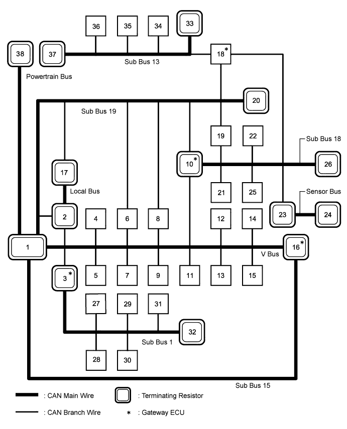
No. ECU/Sensor Name 1 ECM 2 Front steering control ECU 3 Main body ECU (multiplex network body ECU) 4 Parking brake ECU assembly 5 Headlight swivel ECU assembly (AFS ECU) 6 Power steering ECU assembly 7 Center airbag sensor assembly 8 Brake actuator assembly (skid control ECU) 9 Yaw rate sensor 10 Network gateway ECU 11 Multi-media module receiver assembly 12 Combination meter assembly 13 Spiral with sensor cable sub-assembly (steering angle sensor) 14 Air conditioning amplifier assembly 15 DLC3 16 Certification ECU (smart key ECU assembly) 17 Rear steering control ECU 18 Driving support ECU assembly*1 19 Absorber control ECU*2 20 No. 10 junction connector 21 Clearance warning ECU assembly*3 22 Seat belt control ECU*4 23 Blind spot monitor sensor RH*5 24 Blind spot monitor sensor LH*5 25 Telematics transceiver*11 26 No. 9 junction connector 27 Luggage closer motor assembly*6 28 Front multiplex network door ECU LH 29 Front multiplex network door ECU RH 30 Multiplex tilt and telescopic ECU 31 Position control ECU assembly LH 32 No. 11 junction connector 33 Millimeter wave radar sensor assembly*1 34 Lane recognition camera sensor assembly*7 35 Driver monitor ECU assembly*8 36 No.1 night view ECU*9 37 No. 12 junction connector 38 Transmission control ECU assembly*10
-
*1: w/ Dynamic Radar Cruise Control System
-
*2: w/ Adaptive Variable Suspension System
-
*3: w/ LEXUS Parking Assist-sensor System
-
*4: w/ Pre-crash Safety System
-
*5: w/ Blind Spot Monitor System
-
*6: w/ Power Trunk Lid System
-
*7: w/ Lane-keeping Assist System
-
*8: w/ Driver Monitor Camera
-
*9: w/ Night View System
-
*10: for AA81E
-
*11: w/ Telematics Transceiver
Tech Tips
-
The network gateway ECU functions as a gateway between the V bus and sub bus 18 or V bus and sub bus 19.
-
The main body ECU (multiplex network body ECU) functions as a gateway between the V bus and sub bus 1.
-
The driving support ECU assembly functions as a gateway between the sub bus 13 and sub bus 18 or sub bus 13 and sub bus 19.
-
The certification ECU (smart key ECU assembly) functions as a gateway between the V bus and sub bus 15.
-
Refer to the following bus wiring diagrams for details.
-
-
-
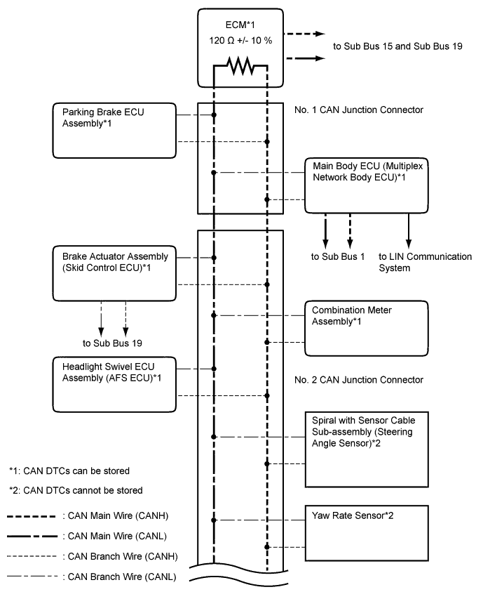
V Bus
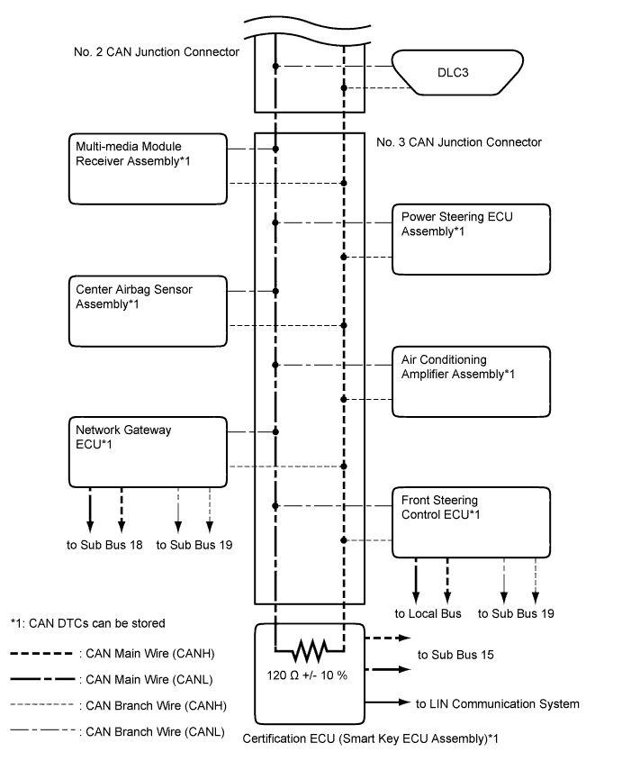
Tech Tips
The CAN communication system connects to other networks via ECUs that function as a gateway Click here.
-
Sub Bus 18
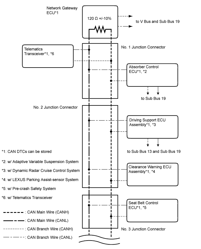
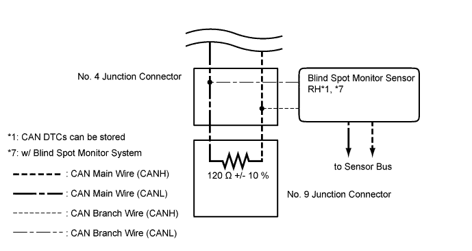
-
Sub Bus 19
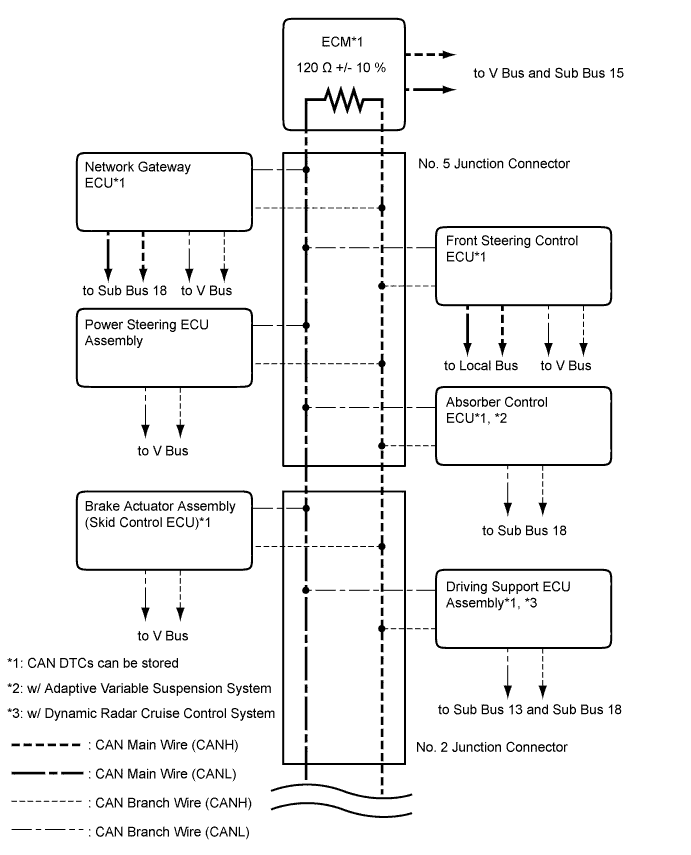
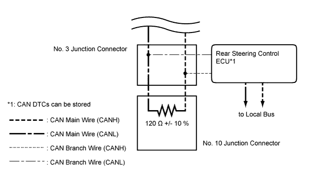
-
Sub Bus 1
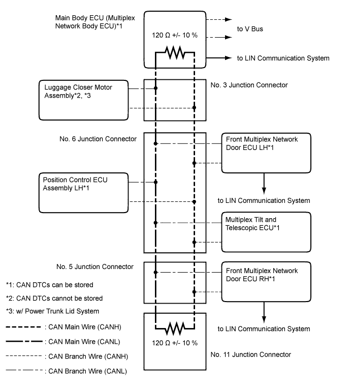
Tech Tips
The CAN communication system connects to other networks via ECUs that function as a gateway Click here.
-
Sub Bus 13 (w/ Dynamic Radar Cruise Control System)
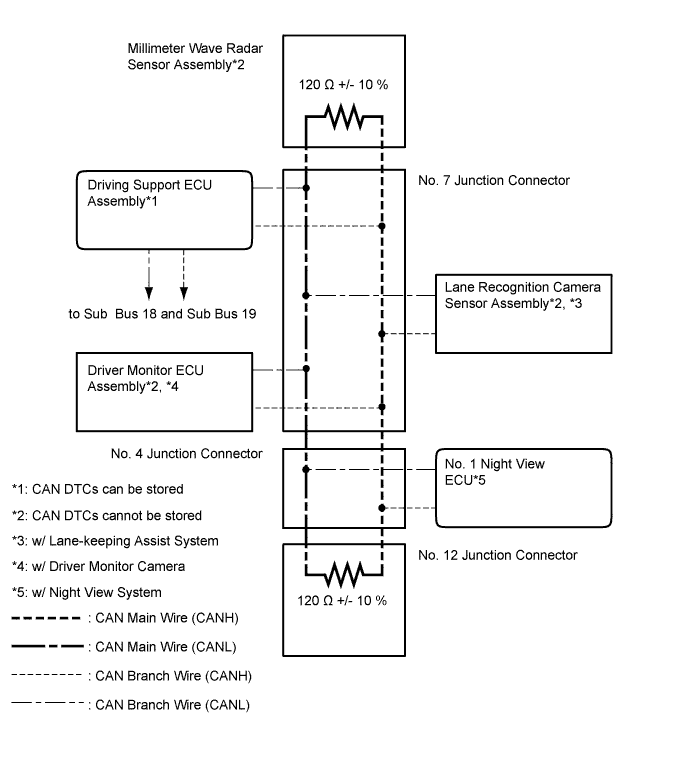
-
Sub Bus 15
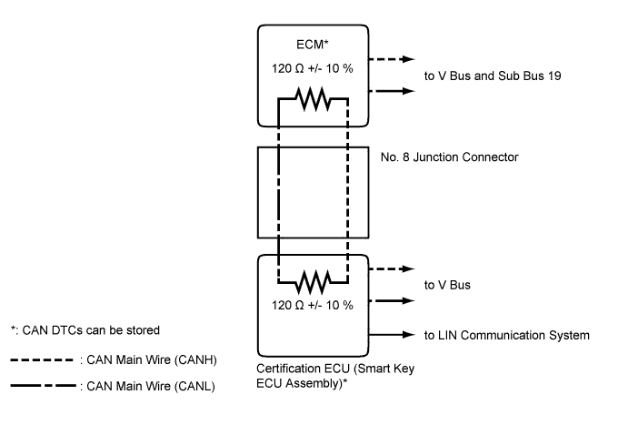
Tech Tips
The CAN communication system connects to other networks via ECUs that function as a gateway Click here.
-
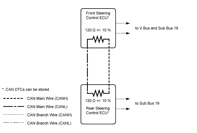
Local Bus
-
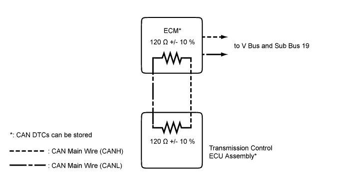
Powertrain Bus (for AA81E)
-
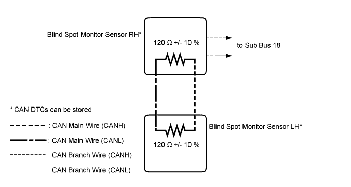
Sensor Bus (w/ Blind Spot Monitor System)
-